1. Introduction
This manual provides detailed instructions for the installation, operation, and maintenance of your LiTime 20Amp PWM 12V/24V Solar Charge Controller. Please read this manual thoroughly before using the product to ensure proper function and safety.

Image 1.1: LiTime 20Amp PWM Solar Charge Controller and its packaging.
2. Key Features
- Wide Compatibility: Supports 12V/24V lithium (LiFePO4) and lead-acid batteries (FLA, GEL, SEL).
- High Solar Input: Handles up to 340W for 12V systems and 680W for 24V systems.
- LCD Display: Provides real-time monitoring of solar, battery, and load status.
- USB Output: Integrated 5V/1A USB port for charging small devices.
- Direct DC Load Control: Connect DC devices directly with real-time or timer modes.
- Compact Design: Small footprint (5.12 × 3.54 × 1.36 inches) and lightweight (0.46 lb) for easy installation.
3. Safety Instructions
Please observe the following safety precautions during installation and operation:
- Ensure all connections are correct and secure before powering on the system.
- Do not expose the controller to water or high humidity. This product is not waterproof.
- Install the controller in a well-ventilated area, protected from direct sunlight and high temperatures.
- The controller includes multiple protections:
- PV over-voltage protection
- PV over-current protection
- PWM over-temperature protection
- Battery over-voltage protection
- Battery reverse polarity protection
- Battery over-discharge protection
- Short circuit protection
- Overload protection
- Always connect the battery first, then the solar panel, and finally the load. Disconnect in reverse order.
- Consult a qualified professional if you are unsure about any installation steps.

Image 3.1: The controller features multiple built-in protections for safe operation.
4. What's in the Box
Upon opening the package, verify that all components are present:
- 1x LiTime 20Amp PWM Solar Charge Controller
- 1x Controller Bracket
- 1x Product Manual
- 2x Nuts M3
- 2x Screws 3*15mm
- 2x Plastic Anchors 4*20mm
- 2x Screws PM3*6mm (for support backplate)
- 2x Screws PM3*12mm (for fixed bracket)

Image 4.1: All items included in the product package.
5. Parts Identification
Familiarize yourself with the components of the solar charge controller:

Image 5.1: Labeled diagram of the solar charge controller's components.
- Panel Mounting Holes: For securing the controller.
- LCD Screen: Displays system status and settings.
- USB Port (5V/1A): For charging mobile devices.
- Operation Buttons: For navigating menus and adjusting settings.
- DC Load Terminals: Connect DC loads (e.g., lights, fans).
- Battery Terminals: Connect to the battery bank.
- Solar Terminals: Connect to the solar panel array.
- Bracket Holes: For attaching the mounting bracket.
- Wall Mounting Holes: For direct wall mounting.
- Bracket Connection Posts: For securing the bracket.
- Panel Mounting Posts & Bolts: Hardware for panel mounting.
- Wall Mounting Screws & Plastic Anchors: Hardware for wall mounting.
6. Installation and Setup
6.1 Mounting the Controller
Choose a vertical surface protected from direct sunlight, high temperatures, and water. Ensure good ventilation around the controller.

Image 6.1: Optional panel mount and wall mount installation methods.
6.2 Wiring Connections
Follow the connection order carefully to prevent damage:
- Connect the Battery: Connect the battery to the battery terminals (positive to positive, negative to negative). The LCD will light up.
- Connect the Solar Panel: Connect the solar panel to the solar terminals (positive to positive, negative to negative).
- Connect the DC Load: Connect the DC load to the load terminals (positive to positive, negative to negative).
Important: Disconnect in the reverse order: load, then solar panel, then battery.

Image 6.2: Example wiring diagram for a solar power system.
6.3 Battery Type Selection
It is crucial to select the correct battery type for optimal charging and battery longevity. The controller supports LiFePO4 (Lithium), FLA (Flooded), GEL, and SEL (Sealed) batteries.
- Enter Set Mode: Press and hold the first button (usually the 'Menu' or 'Set' button) for a few seconds to enter the settings menu.
- Choose Parameters: Short press the second button (usually 'Up' or 'Select') to cycle through the available battery types (LI, FLD, GEL, SEL).
- Save Setting: Once the desired battery type is displayed, press and hold the first button again to save the setting and exit.
Note: For 12V lithium batteries, the default setting is often suitable. For other battery types or 24V systems, ensure you manually select the correct type. Only FLD, GEL, and SEL battery types support automatic recognition of 12V/24V system voltage.
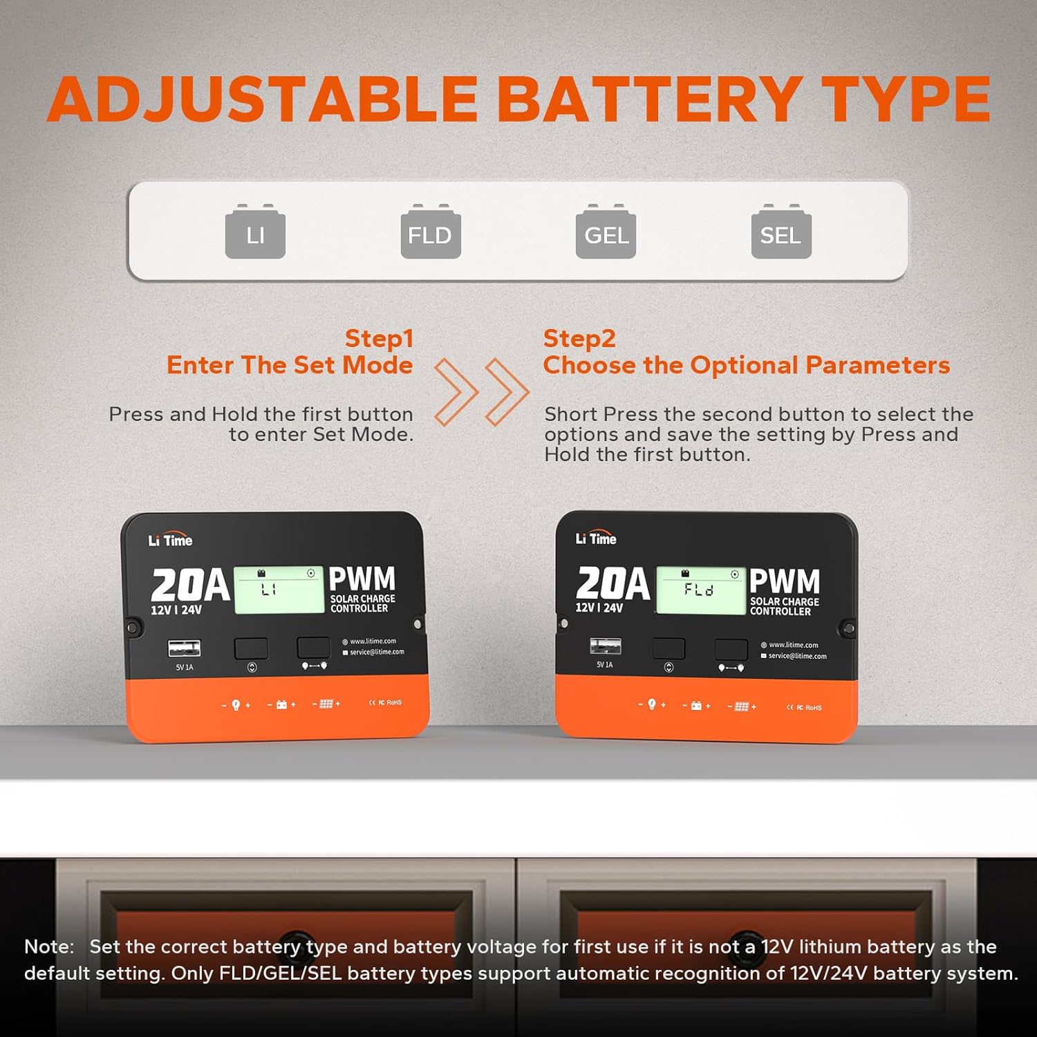
Image 6.3: Steps for adjusting the battery type setting.
7. Operation
7.1 LCD Display Information
The LCD screen cycles through various parameters, providing real-time system status:
- Incoming Solar Voltage
- Battery Voltage
- Battery Charging Amperage
- Load Output Amperage
- Battery State of Charge (SOC)
- Controller Temperature
7.2 USB Output
The 5V/1A USB port can be used to charge small electronic devices such as smartphones or tablets. This output is controlled by the load switch.
7.3 DC Load Control Modes
The controller offers various modes for controlling the DC load output:
- Mode 15 (Manual): The load output is manually actuated. Press the load button to turn it on or off.
- Mode 17 (Always On): The load output remains continuously on.
- Mode 0 (Daylight Off): The load turns on only when no daylight is detected (i.e., when no power is coming from the solar panel).
- Modes 1-14 (Timer Off): The load turns on when no daylight is detected and remains on for the set number of hours (1 to 14 hours) before turning off.
- Mode 16 (Testing Mode): The load turns on and off in quick succession for testing purposes.
To change the load control mode, enter the set mode (as described in Section 6.3) and navigate to the load mode setting.
8. Maintenance
To ensure optimal performance and longevity of your solar charge controller, perform the following maintenance checks periodically:
- Cleanliness: Keep the controller clean and free from dust and debris. Use a dry cloth for cleaning.
- Connections: Periodically check all wiring connections for tightness and corrosion. Loose connections can cause overheating and system malfunction.
- Ventilation: Ensure that the ventilation openings are not blocked to prevent overheating.
- Environmental Conditions: Verify that the controller remains in a dry, well-ventilated area, protected from extreme temperatures and moisture.
9. Troubleshooting
This section addresses common issues you might encounter with your solar charge controller.
| Problem | Possible Cause | Solution |
|---|---|---|
| LCD screen is off. | No battery connected or battery voltage is too low. | Ensure the battery is properly connected and has sufficient charge. |
| Battery not charging. |
|
|
| Load not working. |
|
|
| Controller overheating. | Poor ventilation or excessive load/solar input. | Ensure proper ventilation. Reduce load or check solar input limits. |
10. Specifications
| Parameter | Value |
|---|---|
| Model | 20Amp PWM Solar Charge Controller |
| System Voltage | 12V/24V Auto-recognition (for FLD/GEL/SEL) |
| Rated Charge Current | 20A |
| Rated Load Current | 20A |
| Max Solar Input Voltage | <55V |
| Max Solar Input Power | 340W (12V system) / 680W (24V system) |
| Recommended Solar Open Circuit Voltage | 18V for 12V system, 36V for 24V system |
| USB Output | 5V/1A |
| Display Type | LCD |
| Operating Temperature | -20°C to +55°C (approximate, based on typical ranges) |
| Product Dimensions (L x W x H) | 5.12 x 3.54 x 1.36 inches (130 x 90 x 34.6 mm) |
| Item Weight | 0.46 lbs (5.3 ounces / 0.21 kg) |
| Material | Acrylonitrile Butadiene Styrene (ABS) |
| Certifications | RoHS, CE |

Image 10.1: Physical dimensions and weight of the controller.
11. Warranty and Support
The LiTime 20Amp PWM Solar Charge Controller is backed by a 3-year warranty. For technical assistance or warranty claims, please contact LiTime customer support.
- Website: www.litime.com
- Email Support: service@litime.com
- Technical Support: technicalsupport@litime.com


