1. Introduction
The 100 BALANCE DALY BMS (Battery Management System) is an intelligent active balance BMS designed for 4S to 8S LiFePO4, Li-ion, and LTO battery packs. It provides comprehensive protection and management features to ensure the safety and longevity of your battery system. This BMS includes built-in Bluetooth connectivity, 1A continuous active cell balancing, and supports RS485 and CAN communication protocols.

Image: The 100 BALANCE DALY BMS, highlighting its 4S-8S cell compatibility, 100A current rating, and support for Bluetooth, RS485, and CAN communication.
Key Features:
- Enhanced Battery Safety: Offers protection against overcharging, over-discharging, overcurrent, short circuits, and extreme temperatures.
- Active Cell Balancing: Features continuous 1A active balancing current with a peak current up to 1.2A, ensuring cell voltage uniformity.
- Smart Management: Monitor and adjust settings via Android or iOS mobile app using Bluetooth, or through PC software.
- Voltage Compatibility: Compatible with 4S, 6S, and 8S battery packs (12V, 24V).
- Communication Protocols: Supports Bluetooth, UART, RS485, and CAN for versatile integration.
- Additional Protection: Includes pre-charge protection, wrong/missing connection detection, and parallel connection current limiting.
2. Setup: Wiring Installation
Proper wiring is critical for the safe and correct operation of your BMS. Always ensure all connections are secure and follow the sequence strictly to prevent damage.
2.1. Pre-Installation Checks
- Verify the total positive and total negative terminals of your battery pack.
- Ensure the battery pack is assembled correctly (e.g., 8-string battery pack).
2.2. Wiring Sequence
- Connect the black wire of the sampling cable to the total negative terminal of the battery pack.
- Connect the red wires of the sampling cable to the positive terminals of each cell string, starting from the first string (B1+, B2+, etc.) in sequential order.
- When soldering the wires, ensure they are soldered in the correct order before plugging into the BMS.
- Seal any unused or excess sampling cables with insulation tape.
- Use a multimeter to measure the voltage of the wiring harness to ensure consistency and correctness before connecting to the BMS.
- Plug the NTC (Negative Temperature Coefficient) cable into the NTC-A port on the BMS.
- Connect the B- cable from the BMS to the total negative terminal of the battery pack.
- Insert the sampling wire harness into the designated port on the BMS.
Important Safety Note: Follow the wiring sequence strictly. If the wiring sequence is reversed, it can lead to BMS damage. Miswiring protection is limited to 6 strings; more than 6 strings miswired will damage your BMS.
Video: Detailed introduction and wiring guide for the 100 BALANCE Smart Active Balance BMS. This video demonstrates the step-by-step process of connecting the BMS to a battery pack, including soldering and verification with a multimeter.
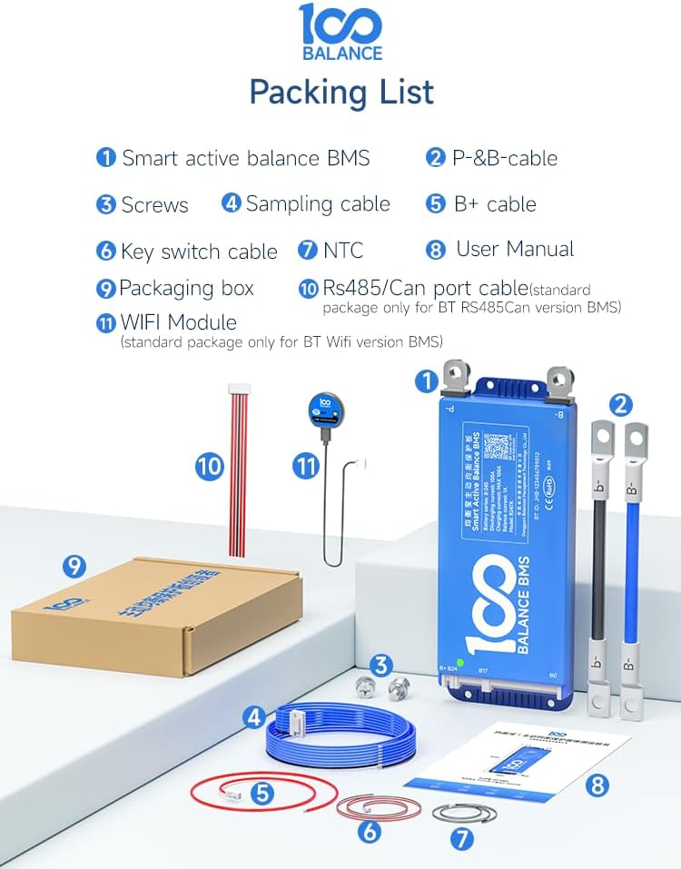
Image: The complete packing list for the BMS, including the Smart Active Balance BMS unit, P-&B- cables, screws, sampling cable, B+ cable, NTC sensor, user manual, packaging box, RS485/CAN port cable, and WiFi module.
3. Operating the BMS
3.1. Using Accessories
The BMS supports various accessories for enhanced functionality and monitoring:
- UART Cable: Supports PC connection for monitoring and parameter settings.
- RS485/CAN: For advanced communication with other systems like inverters.
- LCD Screen: Displays real-time battery information and allows parameter changes via a 4.3-inch touch screen.
- Key Switch: Can be used to switch the discharge MOSFETs on and off. Other functions can be customized.
- Heating Module: Used in cold environments to start the BMS, ensuring optimal performance.
- WiFi Module: Enables remote control and monitoring.
- Inverter Cable: Allows direct connection to compatible inverters.
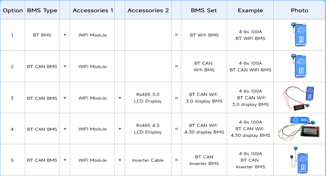
Image: A typical BMS set illustrating the main unit connected to a WiFi module and an LCD display for monitoring and control.

Image: The BMS unit with a connected WiFi module, demonstrating remote monitoring capabilities via a smartphone application.
3.2. Mobile App Operation (Bluetooth)
The BMS features built-in Bluetooth for easy management via a mobile application (Android/iOS). The app allows you to:
- Monitor real-time battery status (voltage, current, temperature, SOC).
- Adjust various BMS settings.
- Control charge/discharge functions.
Video: An introduction to the 100 BALANCE Smart Active Balance BMS, showcasing its features including Bluetooth connectivity and mobile app interface for monitoring and control.
3.3. PC Software Operation
For detailed monitoring, parameter configuration, and firmware upgrades, connect the BMS to a PC using a UART, RS485, or CAN cable.
- Download PC Host Software: Obtain the PC Host software and necessary drivers (for CAN or RS485) from the official 100 BALANCE website or customer service.
- Connect BMS to PC: Use the appropriate communication cable (e.g., UART cable) to connect the BMS to your computer.
- Launch PC Host Software: Open the PC Host application.
- Establish Connection: In the software, select the correct communication port (COM port for UART/RS485) and baud rate (e.g., 9600 for UART/RS485, 250 for CAN). Click 'Open' or 'Connect'.
- Monitor Data: The 'Live Data' screen displays real-time battery information including total voltage, current, temperature, SOC, cell voltages, and MOS temperature.
- Set Parameters: Access the 'Set Parameter' page to configure balance current, sleep time, rated capacity, and protection parameters. Enter the default password (20211115) to enter management mode.
- Current Calibration: In the 'Engineering' interface, you can calibrate the current to ensure accurate readings.
- View History Data: The 'His Data' page allows you to view battery alarm information. You can also clear history data.
- BMS Upgrade: Use the 'BMS Upgrade' function to load firmware files and update your BMS.
Video: A tutorial demonstrating how to connect the 100 BALANCE Smart BMS to a PC host, including software download, connection setup, and navigating the main interface for data monitoring and parameter settings.
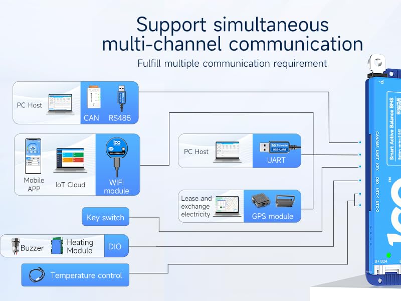
Image: A comprehensive diagram illustrating the multi-channel communication support of the BMS, including connections to PC hosts, mobile apps, IoT cloud, and various external modules.
4. Maintenance: Parallel Connection Precautions
When connecting multiple battery packs in parallel, specific precautions must be taken to ensure safety and proper operation:
- Voltage Matching: Ensure that the voltage of each battery pack is the same before connecting them in parallel. The voltage difference should be less than 1 volt.
- Disconnect Discharging MOSFETs: Before connecting battery packs in parallel, manually disconnect the discharging MOSFETs using the Bluetooth APP or PC software. This prevents high current surges that could trigger short-circuit protection or damage the BMS.
- Parallel Module: The parallel module ensures that the voltage is consistent across each battery pack in a parallel configuration.

Image: Visual representation of the BMS's quadruple extra protection features, including parallel protection, pre-charge protection, misconnection protection, and overall system protection.
5. Troubleshooting
If you encounter issues with your 100 BALANCE DALY BMS, consider the following troubleshooting steps:
- BMS Enters Protection Mode: If the BMS frequently enters protection mode (e.g., due to high current draws from devices like spot welders), verify that the current settings in the app/PC software are appropriate for your application. For devices with high surge currents, it may be necessary to adjust protection thresholds or ensure the load is within the BMS's continuous and peak current limits.
- Cell Imbalance: The 1A active balancer should maintain cell voltage uniformity. If significant cell voltage differences persist, check the sampling wire connections for looseness or corrosion. Ensure the balancing function is enabled in the app/PC software. Balancing is triggered when cells reach the open voltage and there is a voltage difference (default 0.01V).
- Communication Issues: If the mobile app or PC software cannot connect to the BMS, ensure Bluetooth is enabled on your device, the communication cables are securely connected, and the correct drivers are installed for PC communication.
- Miswiring Damage: Be aware that miswiring, especially with more than 6 strings, can permanently damage the BMS. Always double-check wiring with a multimeter before final connection.
- SOC Calibration: For accurate State of Charge (SOC) readings, the BMS will calibrate to 100% SOC when a single cell overvoltage protection level 2 is triggered.
6. Specifications
| Feature | Value |
|---|---|
| Model Number | 100BALANCE 100A 4-8S |
| Battery Series Compatibility | 4S - 8S |
| Continuous Discharge Current | 100A |
| Max Discharge Current (Delay Time: 1±0.8s) | 150A |
| Continuous Charge Current | 100A |
| Active Cell Balancing Current | 1A (Continuous), 1.2A (Peak) |
| Communication Interfaces | Bluetooth, UART, RS485, CAN |
| Input Voltage | 48 Volts (Compatible with 12V, 24V battery packs) |
| Output Voltage | 24 Volts (DC) |
| Item Weight | 15.9 ounces (450 Grams) |
| Package Dimensions | 8.27 x 5.91 x 1.57 inches |

Image: Detailed product specifications including physical dimensions (167mm x 65mm x 15mm) and weight (250g), along with compatible battery types and string configurations.
7. Warranty and Support
The 100 BALANCE DALY BMS comes with a 3-year warranty.
For technical support, troubleshooting assistance, or warranty claims, please contact the manufacturer or your authorized dealer. Refer to the contact information provided in your product packaging or on the official 100 BALANCE website.