1. Introduction
The jojofuny Water Tank Level Gauge is an advanced ultrasonic sensor system designed to monitor the liquid level and temperature of your outdoor water tank from the comfort of your indoor living space. This device provides real-time data, including water level displayed on a 10-bar graph, indoor temperature, and tank temperature, along with time display and alarm functions.
Package Contents:
- 1 x Liquid Level Meter (Receiver Display Unit)
- 1 x Ultrasonic Sensor Transmitter Unit
- Note: Batteries are not included and must be purchased separately.
2. Safety Information
Please read and understand all safety instructions before operating this device. Failure to follow these instructions may result in damage to the product or personal injury.
- Do not expose the device to extreme temperatures, direct sunlight, or excessive moisture.
- Do not attempt to disassemble or modify the device. There are no user-serviceable parts inside.
- Use only the specified battery type (AAA for the receiver unit). Ensure correct polarity when inserting batteries.
- Keep the device out of reach of children.
- Dispose of old batteries responsibly according to local regulations.
- Ensure the ultrasonic sensor transmitter unit is securely installed on the water tank to prevent accidental submersion or damage.
3. Product Components
3.1 Receiver Display Unit
This unit displays all the information from the sensor, including water level, temperatures, and time. It features a clear LCD screen and control buttons.

Figure 3.1: Front view of the Receiver Display Unit.

Figure 3.2: Back view of the Receiver Display Unit, highlighting wall-mounting options.

Figure 3.3: Receiver Display Unit with kickstand extended for standing.
3.2 Ultrasonic Sensor Transmitter Unit
This unit is installed on top of your water tank. It uses ultrasonic technology to measure the water level and temperature within the tank and wirelessly transmits this data to the receiver display unit.

Figure 3.4: Ultrasonic Sensor Transmitter Unit.
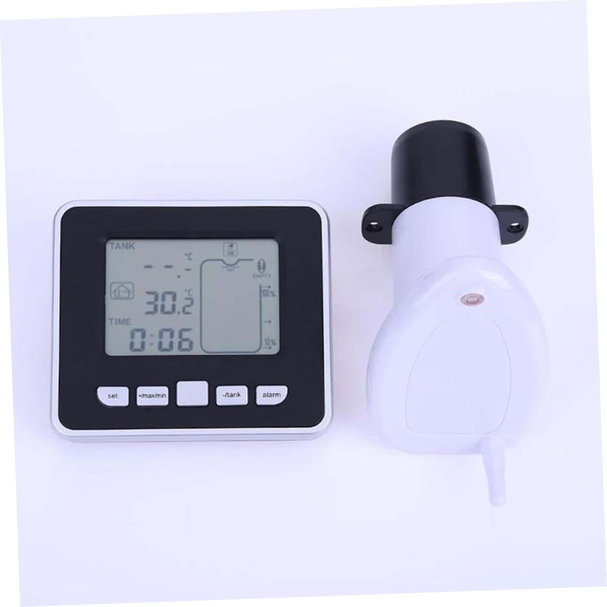
Figure 3.5: Receiver Display Unit and Transmitter Unit.
4. Setup
4.1 Receiver Display Unit Setup
- Install Batteries: Open the battery compartment cover on the back of the receiver unit. Insert 3 x AAA batteries (not included), ensuring correct polarity (+/-). Close the battery cover securely.

Figure 4.1: Battery installation in the Receiver Display Unit.
- Placement: You can place the receiver unit in one of two ways:
- Wall Mount: Use the integrated hooks on the back of the unit to hang it on a wall.
- Standing: Pull out the integrated stand on the back of the unit to place it on a flat surface such as a kitchen benchtop, table, or desk.
4.2 Ultrasonic Sensor Transmitter Unit Installation
- Mounting Location: Install the transmitter unit at the top of your water tank. Ensure the ultrasonic sensor faces downwards towards the water surface.
- Air Gap: Maintain a minimum air gap of 0.5 meters (1.64 feet) between the sensor and the maximum water level. This ensures accurate readings.
- Secure Installation: Ensure the transmitter unit is securely fastened to prevent it from falling into the tank or being dislodged by wind or other environmental factors.
- Initial Pairing: Once both units are powered on and within range (up to 100m in open field), they should automatically establish a connection. The receiver unit will begin displaying tank level and temperature data.
5. Operating Instructions
5.1 Understanding the Display
The LCD screen provides comprehensive information at a glance. Refer to the diagram below for a detailed explanation of each display segment.

Figure 5.1: LCD Display Overview.
| No. | Description |
|---|---|
| 1. | Value display area (for tank level/depth) |
| 2. | Tank temperature and water level icon |
| 3. | Water level unit (Meters/Feet) |
| 4. | Tank temperature unit (°C/°F) |
| 5. | Outdoor low battery indicator (for transmitter unit) |
| 6. | Alarm activation icon |
| 7. | Min. and max. record indicator |
| 8. | Empty alert icon |
| 9. | RF signal indicator |
| 10. | Tank level high and low alarm indicator |
| 11. | Water tank depth icon (10-bar graph) |
| 12. | Time alarm indicator |
| 13. | Time and alarm value display area |
| 14. | Indoor temperature value display area |
| 15. | Indoor temperature unit (°C/°F) |
5.2 Control Buttons
The receiver unit has four control buttons:
- SET: Used to enter settings mode and confirm selections.
- +/MAX/MIN: Used to increase values, view maximum records, or view minimum records.
- -/TANK: Used to decrease values or switch between tank level display modes/units.
- ALARM: Used to set or activate/deactivate alarms.
5.3 Basic Operation
- Viewing Data: The display automatically updates tank level and temperature data every 30 seconds or 3 minutes.
- Changing Temperature Units: Press the SET button to cycle between Celsius (°C) and Fahrenheit (°F) for both indoor and tank temperatures.
- Viewing Min/Max Records: Press the +/MAX/MIN button to cycle through minimum and maximum recorded indoor and tank temperatures.
- Setting Time:
- Press and hold the SET button until the time display flashes.
- Use +/MAX/MIN and -/TANK to adjust the hour and minute.
- Press SET to confirm each setting.
- You can also switch between 12-hour and 24-hour formats.
- Setting Tank Level Alarms (High/Low/Empty):
- Press the ALARM button to enter alarm setting mode.
- Use +/MAX/MIN and -/TANK to set the desired high or low water level alarm thresholds.
- You can also set an "empty tank" alert.
- Press ALARM again to activate or deactivate the set alarms. The alarm activation icon (6) will appear when active.
6. Maintenance
- Cleaning: Wipe the receiver display unit and the exterior of the transmitter unit with a soft, damp cloth. Do not use abrasive cleaners or solvents.
- Battery Replacement: When the low battery indicator appears on the display (for either indoor or outdoor unit), replace the batteries promptly. For the receiver unit, follow the steps in Section 4.1. For the transmitter unit, refer to its specific battery compartment (usually located on the top or side).
- Sensor Check: Periodically inspect the ultrasonic sensor on the transmitter unit for any debris or obstructions that might affect its accuracy.
7. Troubleshooting
| Problem | Possible Cause | Solution |
|---|---|---|
| No display on receiver unit. | Batteries are dead or incorrectly installed. | Replace batteries, ensuring correct polarity. |
| No tank level reading / "---" displayed. |
|
|
| Inaccurate water level readings. |
|
|
| Alarm not sounding. | Alarm not activated or set incorrectly. | Review Section 5.3 on setting and activating alarms. |
8. Specifications
| Feature | Detail |
|---|---|
| Model Number | C233218T8XY99YQPZP5X |
| Material | Plastic |
| Receiver Unit Dimensions (L x W x H) | 10.5 x 9.3 x 2.5 cm (approx. 4.13 x 3.66 x 0.98 inches) |
| Item Weight | 8 ounces |
| Water Level Range | 0.5m to 15m (1.64 ft to 49.2 ft) |
| Air Gap (Min.) | 0.5m (1.64 ft) |
| Transmission Range | Up to 100m (328 ft) in open field |
| Temperature Display | Indoor and Tank Temperature (°C/°F) |
| Time Display | 12/24 hour format |
| Data Update Frequency | Every 30 seconds or 3 minutes |
| Power Source (Receiver) | Batteries (Not Included) - 3 x AAA recommended based on image |
| Mounting Type | Wall Mount, Standing |
9. Warranty Information
According to the product specifications, this product is sold without a manufacturer's warranty. Please refer to the retailer's return policy for any issues or concerns regarding your purchase.
10. Customer Support
For any questions, technical assistance, or issues not covered in this manual, please contact the seller or the manufacturer, jojofuny, through the platform where you purchased the product. Please have your model number (C233218T8XY99YQPZP5X) and purchase details ready when contacting support.