
1. Introduction
This instruction manual provides essential information for the safe and effective use of the Cleiscry 3W UV LED Chips. These high-power ultraviolet light-emitting diodes are designed for various applications requiring UV light in the 365-370nm range. Please read this manual thoroughly before installation and operation.
2. Safety Information
- UV Radiation Warning: Ultraviolet (UV) light can be harmful to eyes and skin. Avoid direct exposure to the UV light emitted by these LEDs. Always wear appropriate UV protective eyewear and skin protection when operating these LEDs.
- Electrical Safety: These are electrical components. Ensure all power connections are made correctly and safely. Incorrect wiring can cause damage to the LEDs or pose an electrical hazard. Disconnect power before installation or maintenance.
- Heat Management: 3W LEDs generate significant heat. Proper heat dissipation is critical for the longevity and performance of the LED. Always use an adequate heat sink system to keep the LED's operating temperature below 60°C (140°F). Failure to do so will drastically reduce the LED's lifespan and may cause immediate failure.
- Handling: Handle LED chips with care. Avoid touching the optical lens surface to prevent contamination or damage. Use anti-static precautions when handling.
- Children and Pets: Keep LED chips and associated components out of reach of children and pets.
3. Product Overview
The Cleiscry 3W UV LED Chips are high-power ultraviolet light sources. Each package contains 10 individual LED chips, designed for integration into custom lighting solutions.

Image 3.1: A pack of 10 Cleiscry 3W UV LED Chips, as supplied.
Each LED chip features a robust design with double golden wire (99.99%) and a copper frame for enhanced reliability and thermal performance.
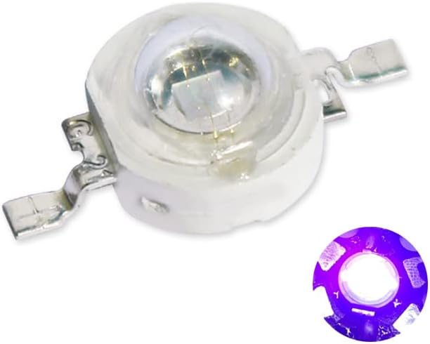
Image 3.2: Close-up view of a single Cleiscry 3W UV LED Chip, showing its compact design.
4. Specifications
| Parameter | Value |
|---|---|
| Quantity per package | 10 pieces |
| Power (Max) | 3 Watt |
| Emitting Color | Ultraviolet (UV) |
| Wavelength Range | 365nm - 370nm |
| Forward Voltage (Vf) | 3.0V - 3.8V |
| Recommended Current (If) | 400mA - 700mA |
| Luminous Output (UV) | Up to 370 Lumens (Note: Lumens for UV are a measure of radiant power, not visible brightness) |
| Emitting Angle | 120-140 degrees |
| Life Span | 50,000 Hours (with proper heat sink system) |
| Operating Temperature | Below 60°C (140°F) |
| Manufacturer | Cleiscry |
| Model Number | 3W365nm |
| Efficiency | Energy Efficient |

Image 4.1: Technical drawing showing the dimensions of the 3W UV LED Chip.
5. Installation and Setup
These LED chips are components intended for integration into a larger system. Proper installation is crucial for performance and safety.
5.1 Heat Sink Attachment
- Prepare the Heat Sink: Select a heat sink appropriate for 3W power dissipation. The heat sink should be clean and flat.
- Apply Thermal Paste/Adhesive: Apply a thin, even layer of high-quality thermal paste or thermal adhesive to the back of the LED chip or the mating surface of the heat sink.
- Mount the LED: Carefully place the LED chip onto the heat sink, ensuring good contact. Secure it using appropriate methods (e.g., screws if the heat sink has mounting holes, or thermal adhesive if permanent). Ensure the LED is firmly attached and there are no air gaps.
5.2 Electrical Connection
- Identify Polarity: The LED chip has positive (+) and negative (-) terminals. Refer to the technical drawing (Image 4.1) for polarity identification.
- Power Supply: Connect the LED to a constant current power supply that can provide the recommended current (400mA - 700mA) at the forward voltage (3.0V - 3.8V). A constant current driver is highly recommended for optimal performance and longevity.
- Wiring: Solder wires to the LED terminals. Ensure strong, clean solder joints. Use appropriate wire gauge for the current.
- Series/Parallel: If connecting multiple LEDs, consider series or parallel configurations based on your power supply capabilities. For series connections, sum the forward voltages. For parallel connections, sum the currents. Always use current limiting resistors or a constant current driver for each LED or string.
6. Operating Instructions
Once properly installed and connected to a suitable power supply:
- Power On: Apply power from your constant current driver or power supply. The LED should illuminate with UV light.
- Monitor Temperature: During initial operation, monitor the temperature of the heat sink. If the heat sink becomes excessively hot (uncomfortable to touch), the heat dissipation is insufficient, and the LED's lifespan will be reduced. Adjust the heat sink or reduce the operating current if necessary.
- UV Protection: Always ensure UV protective eyewear and skin protection are in place before activating the UV LEDs.
7. Maintenance
These LED chips require minimal maintenance once properly installed.
- Cleaning: If necessary, gently clean the LED lens with a soft, lint-free cloth. Avoid abrasive materials or harsh chemicals.
- Inspection: Periodically inspect the electrical connections and heat sink for any signs of wear, corrosion, or loose connections.
- Temperature Check: Ensure the heat sink remains effective and the LED does not overheat during operation.
8. Troubleshooting
| Problem | Possible Cause | Solution |
|---|---|---|
| LED does not light up |
|
|
| LED is dim or flickers |
|
|
| LED overheats quickly |
|
|
| Short LED lifespan |
|
|
9. Warranty and Support
Cleiscry products are manufactured to high standards. For specific warranty information and technical support, please refer to the retailer or contact Cleiscry customer service through their official channels. Keep your purchase receipt as proof of purchase.