1. Introduction
This manual provides detailed instructions for the Spotpear ESP32-S3-Touch-LCD-1.28 development board. This compact and high-performance microcontroller board integrates a 1.28-inch circular capacitive touchscreen LCD, an ESP32-S3 chip, and essential peripherals including a six-axis sensor (three-axis accelerometer and three-axis gyroscope). It is designed for various embedded applications and development projects.
The ESP32-S3-Touch-LCD-1.28 offers robust wireless connectivity with Wi-Fi and Bluetooth, making it suitable for IoT projects, wearable devices, and interactive displays. Its integrated lithium battery charging chip allows for portable applications.
2. Features
- Microcontroller: ESP32-S3-WROOM-1-N16R8 (ESP32-S3 series)
- Display: 1.28-inch circular LCD, 240x240 pixels, 65K colors, capacitive touchscreen
- Sensors: Integrated six-axis sensor (three-axis accelerometer and three-axis gyroscope)
- Connectivity: Wi-Fi, Bluetooth, USB Type-C interface for power and data
- GPIO: 6 General Purpose Input/Output pins available
- Power: 3.7V lithium battery interface with charging circuit
- Compact Design: Small form factor suitable for embedding
3. Product Overview
3.1. Component Layout

Figure 1: ESP32-S3-Touch-LCD-1.28 Component Layout
This image displays the top-down view of the ESP32-S3-Touch-LCD-1.28 development board, highlighting its key components with numbered labels. These components include the ESP32-S3 module, the 1.28-inch round LCD display connector, the USB Type-C port, battery connector, and various buttons and integrated circuits essential for its operation.
3.2. Pinout Diagram
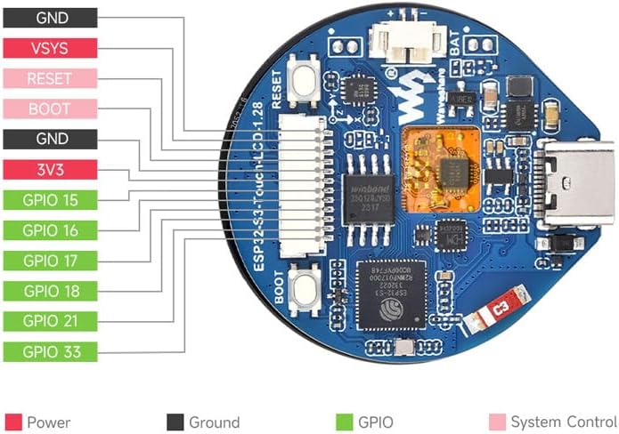
Figure 2: ESP32-S3-Touch-LCD-1.28 Pinout
The pinout diagram illustrates the connections for power, ground, GPIO, and system control pins available on the ESP32-S3-Touch-LCD-1.28 board. This diagram is crucial for connecting external sensors, actuators, or other modules to the development board. It clearly distinguishes between Power (red), Ground (black), GPIO (green), and System Control (pink) pins, providing a clear guide for hardware interfacing.
3.3. Display in Operation

Figure 3: Display in Operation
This image shows the 1.28-inch round LCD display of the ESP32-S3-Touch-LCD-1.28 module in an active state, displaying information such as time, date, and activity metrics. A finger is shown interacting with the touchscreen, demonstrating its touch capability. The display features a vibrant interface with various data points, indicating its potential for use in smartwatches or interactive control panels.
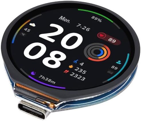
Figure 4: Detailed Display Metrics
This image provides another view of the 1.28-inch round LCD display, showcasing a more detailed set of metrics. It includes information like temperature, battery percentage, heart rate, and various activity tracking data such as steps and calories. The display's clarity and ability to present multiple data points simultaneously highlight its versatility for complex user interfaces.
4. Setup
4.1. Powering On
- USB Power: Connect the ESP32-S3-Touch-LCD-1.28 to a computer or a 5V USB power adapter using a USB Type-C cable. The board will power on automatically.
- Battery Power: For portable applications, connect a 3.7V lithium battery to the dedicated battery connector on the board. The integrated charging circuit will manage battery charging when USB power is connected.
4.2. Connecting to a Host Computer
Use the provided USB Type-C cable to connect the module to your computer. This connection will provide power and establish a serial communication link, which is essential for programming and debugging the ESP32-S3.
4.3. Software Environment Setup
To program the ESP32-S3-Touch-LCD-1.28, you will need to set up a development environment. Popular choices include:
- ESP-IDF (Espressif IoT Development Framework): The official development framework for ESP32 series chips. It provides a comprehensive set of tools and libraries. Refer to the Espressif documentation for installation and usage.
- Arduino IDE: The Arduino environment can be configured to support ESP32 boards, offering a simpler programming interface, especially for beginners. Install the ESP32 board package through the Arduino Boards Manager.
Ensure that the necessary USB drivers for the serial communication chip (often CP210x or CH340) are installed on your operating system.
5. Operating Instructions
5.1. Basic Operation
Once powered and programmed, the module will execute the loaded firmware. Interaction typically occurs via the 1.28-inch capacitive touchscreen. The specific functionalities will depend on the application code you upload.
- Touchscreen: The capacitive touchscreen supports multi-touch gestures, allowing for intuitive user interfaces.
- GPIO: The available GPIO pins can be used to interface with external components such as buttons, LEDs, or other sensors.
- Wireless Communication: Utilize Wi-Fi and Bluetooth capabilities for network connectivity, data transfer, and communication with other devices.
5.2. Programming and Uploading Firmware
- Write Code: Develop your application code using ESP-IDF or Arduino IDE.
- Compile: Compile your code to generate a binary firmware file.
- Connect: Ensure the module is connected to your computer via USB Type-C.
- Upload: Use the respective IDE's upload function or ESP-IDF tools to flash the firmware onto the ESP32-S3. You may need to press the BOOT button while resetting the board to enter download mode, depending on your setup and firmware.
6. Maintenance
The ESP32-S3-Touch-LCD-1.28 module is designed for durability, but proper care ensures longevity.
- Cleaning: Use a soft, dry cloth to clean the display and board. Avoid abrasive materials or harsh chemicals.
- Storage: Store the module in a dry, anti-static environment away from direct sunlight and extreme temperatures.
- Handling: Avoid applying excessive force to the display or connectors. Handle the board by its edges to prevent damage to components.
7. Troubleshooting
- Module Not Powering On:
- Check USB cable connection and power source.
- Ensure the battery is charged if operating on battery power.
- Firmware Upload Failure:
- Verify correct COM port selection in your IDE.
- Ensure USB drivers are installed.
- Try pressing the BOOT button while resetting the board to enter download mode.
- Check for correct board selection in your IDE (e.g., ESP32-S3 Dev Module).
- Display Not Working:
- Ensure the display connector is securely seated.
- Verify that your firmware initializes the display correctly.
- Touchscreen Unresponsive:
- Check for proper touchscreen driver initialization in your code.
- Ensure no physical obstructions are on the screen.
8. Technical Specifications
| Feature | Specification |
|---|---|
| Microcontroller | ESP32-S3-WROOM-1-N16R8 (Dual-core, up to 240 MHz) |
| Display Size | 1.28 inches |
| Display Type | Circular LCD, Capacitive Touchscreen |
| Resolution | 240 x 240 pixels |
| Color Depth | 65K colors |
| Wireless Connectivity | Wi-Fi (802.11 b/g/n), Bluetooth (BLE 5.0) |
| Sensors | Six-axis (3-axis accelerometer, 3-axis gyroscope) |
| GPIO Pins | 6 (user-accessible) |
| Interface | USB Type-C |
| Battery Interface | 3.7V Lithium Battery (with charging circuit) |
| Operating Voltage | 5V via USB, 3.7V via battery |
| Dimensions | Approximately 4.84 x 3.19 x 1.22 inches (Package) |
| Weight | Approximately 1.41 ounces |
9. Warranty and Support Information
For warranty claims, technical support, and additional resources, please refer to the official Spotpear website or contact your retailer. Keep your proof of purchase for warranty validation. Online documentation, example code, and community forums may also be available to assist with development and troubleshooting.


