1. Introduction
This instruction manual provides comprehensive guidance for the proper use and installation of the VCELINK RJ45 CAT6A/CAT7 Pass Through Shielded Connectors and the included RJ45 Crimping Tool. Adhering to these instructions will ensure optimal performance and longevity of your network connections.
2. Package Contents
- 30 × VCELINK RJ45 CAT6A/CAT7 Pass Through Shielded Connectors
- 1 × VCELINK RJ45 Pass Through Crimping Tool

Image 2.1: Overview of the VCELINK RJ45 Pass Through Connectors and Crimping Tool.
3. Specifications
| Component | Specification |
|---|---|
| RJ45 Connectors | CAT6A/CAT7 Shielded, Pass Through |
| Compatible Wire Gauge | 23 AWG (solid and stranded) |
| Compatible Insulation OD | 1.35mm ~ 1.45mm |
| Compatible Cable OD | 7mm ~ 8mm |
| Crimping Tool Compatibility | RJ45 CAT5/5E/6/6A/7, RJ11, RJ12 modular plugs |
| Connector Material | Copper Alloy Shielded Housing, 50µ Gold Plated Contacts |
| Crimping Tool Handle Material | Metal with Ergonomic Grip |

Image 3.1: Illustration of VCELINK RJ45 connector performance, supporting up to 10Gbps and 600MHz with copper alloy shielded housing.

Image 3.2: Detailed view of the connector's internal components, highlighting 50µ gold-plated, nickel-plated, and pure copper chips for optimal conductivity and durability.
4. Setup and Installation
4.1 Cable Compatibility
These CAT6A RJ45 connectors are specifically designed for CAT7 and CAT6A cables, supporting both stranded and solid conductors. Ensure your cable's inner conductor is 23 AWG and has an insulation outer diameter (OD) between 1.35mm and 1.45mm. The overall cable sheath OD should be between 7mm and 8mm. These connectors are not compatible with CAT8, CAT6, CAT5e, or CAT5 cables due to differing core wire thicknesses.
4.2 Wire Preparation
- Carefully strip approximately 2-3 cm (1 inch) of the cable's outer jacket.
- Untwist the wire pairs and straighten each individual wire.
- Arrange the wires according to the T568A or T568B wiring standard. T568B is commonly used.
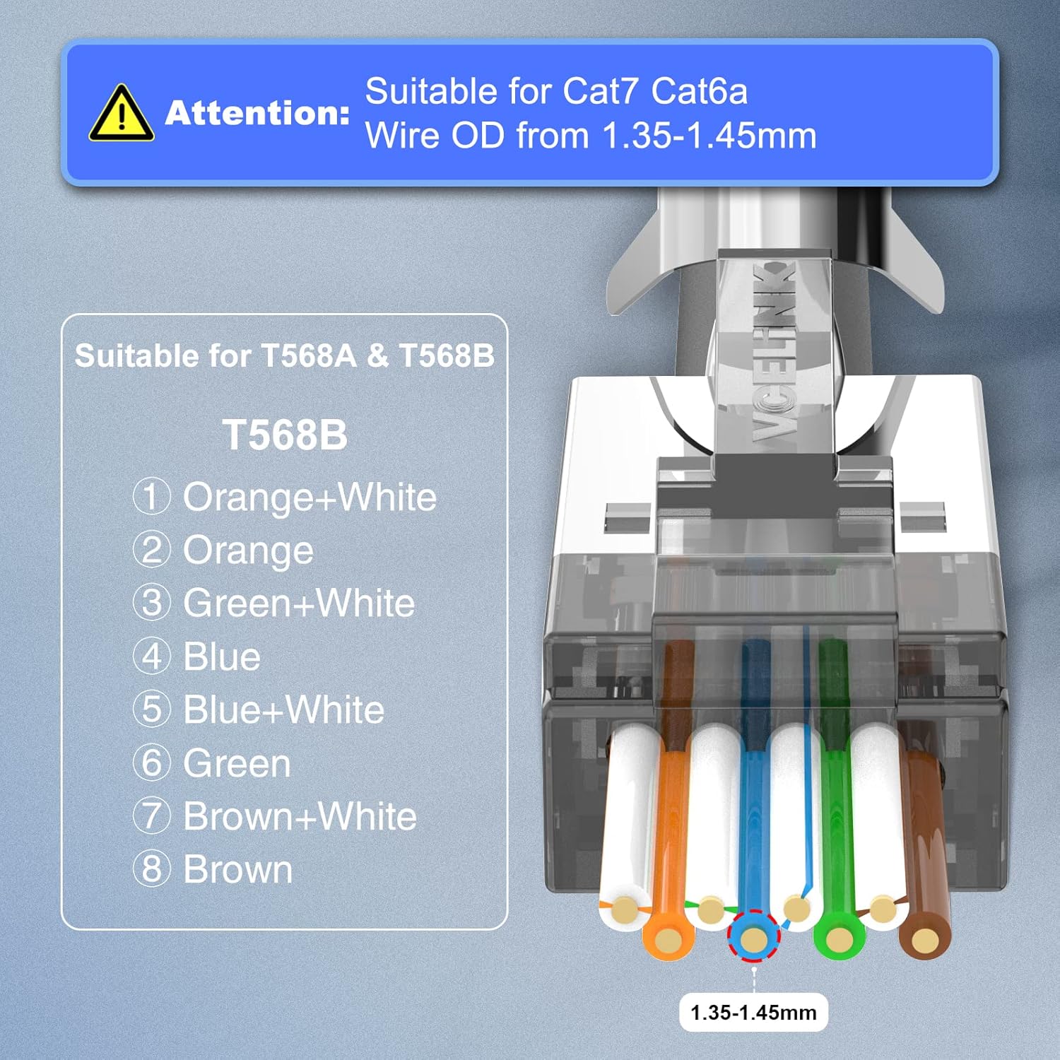
Image 4.1: T568B wiring standard for RJ45 connectors, showing the correct color sequence and emphasizing compatibility with Cat7/Cat6a wires with an OD of 1.35-1.45mm.
4.3 Inserting Wires into Connector
- Insert the arranged wires into the load bar provided with the connector. This helps maintain the correct sequence and spacing.
- Carefully push the wires through the pass-through connector, ensuring each wire passes through its designated channel. The pass-through design allows you to verify the wire sequence before crimping, reducing errors.
- Pull the wires through until the cable jacket is seated firmly inside the connector body, providing strain relief.
5. Operating the Crimping Tool
5.1 Crimping Tool Overview
The VCELINK Multi-Modular Crimping Tool is designed for crimping, cutting, and stripping various modular plugs, including RJ45 CAT7/CAT6/CAT5, RJ11, and RJ12. It is particularly suitable for pass-through and shielded modular plugs, featuring a mechanism to crimp metal dovetail clips.

Image 5.1: The VCELINK RJ45 Crimping Tool, designed for various modular plugs.

Image 5.2: The crimping tool is compatible with CAT5/5E/6/6A/7 RJ45 End Pass Through Plugs.
5.2 Lock/Unlock Mechanism
To unlock the crimping tool, press down on the handles and roll out the lock button. To lock it for storage, press the handles together and roll the lock button into place.

Image 5.3: Instructions for locking and unlocking the crimping tool for safe storage and operation.
5.3 Crimping Process
- Once the wires are correctly inserted through the pass-through connector and the sequence is verified, place the connector into the appropriate RJ45 slot on the crimping tool.
- Ensure the connector is seated firmly and correctly in the tool's cavity.
- Squeeze the handles of the crimping tool firmly and completely until you feel a click. This action simultaneously crimps the contacts, secures the cable, and trims the excess wires protruding from the front of the pass-through connector.
- For shielded connectors, ensure the tool also crimps the metal dovetail clip to provide proper grounding and shielding.
- Release the handles and remove the crimped connector. Inspect the connection to ensure all wires are properly seated and the excess has been cleanly trimmed.

Image 5.4: Step-by-step visual guide for the crimping process, showing before and after crimping results for both shielded and unshielded connectors.
6. Maintenance
To ensure the longevity and reliable performance of your VCELINK crimping tool and connectors, follow these maintenance guidelines:
- Crimping Tool: Keep the tool clean and free of debris. Periodically apply a light machine oil to the pivot points to ensure smooth operation. Store the tool in a dry environment to prevent rust.
- Connectors: Store unused connectors in their original packaging or a clean, dry container to protect them from dust and moisture.
7. Troubleshooting
7.1 No Network Connectivity After Crimping
- Check Wire Sequence: Verify that the wires are arranged correctly according to T568A or T568B standards at both ends of the cable.
- Inspect Crimp: Ensure all 8 pins are fully crimped and making proper contact with the wires. Re-crimp if necessary, or use a new connector.
- Cable Compatibility: Confirm that your cable (CAT7/CAT6A) and its wire OD meet the specifications for these connectors (23 AWG, 1.35-1.45mm insulation OD). Incorrect cable types can lead to poor contact.
- Test Cable: Use a cable tester to identify any breaks or miswires in the cable.
7.2 Wires Slide Out of Connector
- Cable Jacket Seating: Ensure the cable jacket is pushed far enough into the connector body to be gripped by the strain relief.
- Wire Gauge: Verify the wire gauge is 23 AWG. Thinner wires (e.g., from CAT5e/CAT6) may not be securely held by the connector's internal structure.
- Crimping Force: Ensure the crimping tool was fully squeezed during the crimping process.
7.3 Crimping Tool Jams or Does Not Cut Wires Cleanly
- Clear Debris: Check for any wire fragments or debris obstructing the cutting blades or crimping mechanism.
- Lubrication: Apply a small amount of lubricant to the tool's moving parts.
- Blade Wear: If the blades are dull, they may need replacement (if applicable) or the tool may require servicing.
8. Warranty and Support
VCELINK products are manufactured to high-quality standards. For warranty information, technical support, or assistance with product issues, please refer to the VCELINK official website or contact their customer service directly. Keep your purchase receipt for warranty claims.