
PowMr POW-SunSmart 12KL3
Contents
PowMr POW-SunSmart L3 12 kW Hybrid Solar Inverter User Manual
Model: POW-SunSmart 12KL3
1. Introduction
1.1 Product Overview
The PowMr POW-SunSmart L3 series is an advanced 12 kW all-in-one hybrid solar inverter designed for both single-phase and three-phase 48 V DC to 230/400 V AC systems. This innovative device integrates solar energy storage, power load management, and energy storage capabilities, providing a pure sine wave AC output. It features a built-in 260 A MPPT charge controller for efficient solar power utilization.

Figure 1.1: Front view of the PowMr POW-SunSmart L3 Hybrid Solar Inverter, showcasing its sleek design and integrated display.
1.2 Key Features
- 12 kW Rated Output Power: Provides substantial continuous power for various applications.
- Single-Phase and Three-Phase Output: Supports 230V/400VAC pure sine wave output.
- Dual MPPT Charge Controller: Features two Maximum Power Point Tracking inputs with 99.9% efficiency and a maximum current of 22A per circuit, optimized for high-performance modules.
- Wide Battery Compatibility: Compatible with AGM, Gel, Lead-Acid, Lithium, and LiFePO4 batteries. Supports batteryless operation.
- Flexible Charging Options: Supports charging from solar, utility grid, or generator.
- Comprehensive Protection: Includes protection against short circuits, overcurrent, overvoltage, overload, and backfill.
- Communication Interfaces: Supports CAN, USB, and RS485 for monitoring and control.
- Adjustable Phase Voltage: Allows adjustment of phase voltage within 200, 208, 220, 230, 240Vac.

Figure 1.2: Visual representation of the inverter's key specifications, including 12kW rated output, 260A max hybrid charging current, and dual MPPT.
1.3 Safety Information
Please read and understand all instructions and warnings before installing, operating, or maintaining this inverter. Failure to follow these instructions may result in electric shock, fire, serious injury, or death. Keep this manual for future reference.
- Installation must be performed by qualified personnel.
- Ensure all power sources are disconnected before any installation or maintenance.
- Do not operate the inverter if it is damaged or appears to be malfunctioning.
- Avoid exposing the inverter to water, excessive humidity, or corrosive environments.
- Ensure proper ventilation around the inverter to prevent overheating.
- Use appropriate personal protective equipment (PPE) during installation and maintenance.
2. Setup and Installation
2.1 Site Selection
Choose a location that is dry, well-ventilated, and protected from direct sunlight, rain, and dust. The ambient temperature should be within the operating range specified in the technical specifications. Ensure sufficient clearance around the inverter for proper airflow.
2.2 Mounting the Inverter
Mount the inverter vertically on a sturdy wall or support structure capable of holding its weight. Use appropriate mounting hardware (not included) and follow local building codes.


Figure 2.1: Side and front views of the inverter, illustrating its physical dimensions and mounting points (not explicitly shown but implied by form factor).
2.3 Electrical Connections
All electrical connections must comply with national and local electrical codes. Ensure correct polarity for DC connections and proper phase sequencing for AC connections.
- PV Input Connection: Connect solar panel strings to the PV input terminals. The maximum PV input power is 9 kW, with a maximum PV input voltage of 650 Vdc and maximum input current of 22 A. Recommended PV wire size is 5 mm²/10 AWG.
- Battery Connection: Connect the 48V battery bank to the battery terminals. The inverter is compatible with AGM, Gel, Lead-Acid, Lithium, and LiFePO4 batteries. It also supports batteryless operation, where the inverter can power loads directly from PV array or AC grid without a connected battery.
- AC Output Connection: Connect your loads to the AC output terminals. The inverter provides 230/400 Vac (single-phase/three-phase) pure sine wave output.
- AC Input Connection (Utility/Generator): Connect the utility grid or a generator to the AC input terminals for charging or backup power.
- Communication Ports: Utilize the CAN, USB, and RS485 ports for external communication and monitoring.

Figure 2.2: Illustration of the inverter's compatibility with various battery types (AGM, GEL, FLD, LI, SLD, USER) and its batteryless operation capability.
3. Operation
3.1 LCD HD Display Screen
The inverter features an intuitive LCD HD display screen that provides real-time operational status and allows for configuration adjustments. The display shows various parameters such as battery capacity, load percentage, system status (normal/alarm/fault), and power sources (utility, generator, solar power, home appliances).

Figure 3.1: Close-up view of the LCD HD display screen, showing various icons and indicators for system status and power flow.
3.2 Navigation and Settings
Use the control buttons located below the display to navigate through menus and adjust settings:
- Enter/Exit Settings: Used to enter or exit the settings menu.
- Option Increase: Used to increase a value or move up in a menu.
- Option Decrease: Used to decrease a value or move down in a menu.
- OK/Enter Options: Used to confirm a selection or enter a sub-menu.
3.3 Charging Modes
The inverter supports four distinct charging modes, allowing flexible management of battery charging based on available power sources:
- Solar First: Prioritizes solar power for charging the battery. Utility power is used only if solar power is insufficient.
- Utility First: Prioritizes utility grid power for charging. Solar power is used only if utility power is unavailable or insufficient.
- Solar and Utility: Uses both solar and utility power simultaneously to charge the battery.
- Only Solar: Charges the battery exclusively from solar power. Utility power is not used for charging.
3.4 Load Output Working Modes
The inverter offers three load output working modes to manage power supply to connected appliances:
- Utility First: Prioritizes utility grid power to supply loads. Battery power is used only when the utility grid is unavailable.
- Solar First: Prioritizes solar power to supply loads. If solar power is insufficient, battery power is used. Utility power is used as a last resort.
- SBU First (Solar-Battery-Utility): Prioritizes solar power, then battery power, and finally utility power to supply loads.

Figure 3.2: Diagram illustrating the four charging modes and three load output working modes of the inverter.
4. Maintenance
4.1 General Maintenance
Regular maintenance ensures optimal performance and longevity of your inverter. Always disconnect all power sources before performing any maintenance.
- Cleaning: Periodically clean the exterior of the inverter with a dry, soft cloth. Ensure ventilation openings are free from dust and debris. The inverter is equipped with a demountable insect screen for easier cleaning.
- Connections Check: Regularly inspect all electrical connections for tightness and signs of corrosion.
- Environmental Check: Ensure the installation environment remains dry, well-ventilated, and free from excessive temperatures or humidity.
4.2 Troubleshooting
If the inverter is not operating as expected, refer to the display for error codes or indicators. Common issues may include:
- No Power Output: Check input power sources (solar, utility, battery) and all circuit breakers.
- Overload Alarm: Reduce the connected load. The inverter has overload protection.
- Battery Low/High Voltage: Check battery connections, voltage, and charging settings.
- PV Input Issues: Verify solar panel connections, shading, and open-circuit voltage.
For persistent issues, consult a qualified technician or contact PowMr customer support.
5. Technical Specifications
| Parameter | Value |
|---|---|
| Brand | PowMr |
| Model Number | POW-SunSmart 12KL3 |
| Rated Output Power | 12000 W (Continuous), 24000 W (Surge) |
| Rated Output Voltage | 230/400 Vac (Single-phase/Three-phase) |
| Switching Time | 10 ms |
| Max. PV Input Power | 9 KW |
| Max. PV Input Voltage | 650 Vdc |
| Max. PV Input Current | 22 A |
| PV Starting Voltage | >150 Vdc |
| Max. Open-circuit Voltage | 800 Vdc |
| Max. Hybrid Charging Current | 260 A |
| Efficiency | 99.9% (MPPT) |
| Display Type | LCD |
| Communication | CAN, USB, RS485 |
| Certifications | CE |
| Recommended Uses | Vehicles, cabins, RVs, boats, backup power during outages |
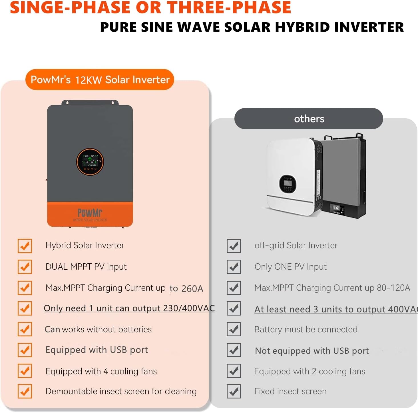
Figure 5.1: Comparison of PowMr's 12kW Solar Inverter features against typical alternatives, highlighting advantages like dual MPPT and 230V/400VAC output from a single unit.
6. Warranty and Support
For warranty information, technical support, or service inquiries, please contact PowMr customer service through their official website or the retailer from whom the product was purchased. Please have your model number (POW-SunSmart 12KL3) and purchase date available when contacting support.
PowMr is committed to providing reliable products and excellent customer service. Regular software updates may be available; please check the manufacturer's website for the latest information.
Ask a question about this manual
Ask about setup, troubleshooting, compatibility, parts, safety, or missing instructions. Manuals+ will review the question and use this page’s manual context to help answer it.