1. Introduction
The PEMENOL GY21309 is a DIY electronic soldering kit designed to assemble a 6-digit digital clock with integrated LED music spectrum effects. This kit serves as an educational tool for learning soldering techniques and circuit understanding, while also providing a functional digital clock that can display time or dynamic music spectrums based on ambient sound.
The device automatically switches between music spectrum display when sound is detected and time display when silent. Users can customize various settings, including 18 music spectrum display modes, brightness, and time format.
2. Product Features
- Six-Digit LED Display: Provides clear timekeeping with support for 12-hour and 24-hour formats.
- 18 Music Spectrum Effects: Dynamic visual effects that respond to sound via a built-in microphone module.
- Automatic Mode Switching: Seamlessly transitions between spectrum display and clock display based on ambient sound levels.
- Adjustable Settings: Customizable spectrum display modes, light flashing speed, display brightness, and sound sensitivity.
- Nighttime Power-saving Mode: Automatically lowers brightness during a user-defined period for comfortable viewing.
- Power-off Memory: Retains settings and time during power interruptions.
- Dual USB Power Supply: Offers flexible power connection options.
- DIY Soldering Project: An engaging kit for enhancing soldering skills, particularly with Surface Mount Device (SMD) components.

Image: The assembled PEMENOL GY21309 digital clock displaying time, with icons illustrating key features such as 12/24H time, USB power, 18 spectral effects, brightness control, and night mode.
3. Package Contents
Upon opening the package, verify that all components are present. The kit typically includes:
- Main PCB (Printed Circuit Board)
- LED Matrix Display Modules (6 units)
- Microcontroller (MCU) chip
- DS1302 Real-Time Clock (RTC) IC
- 32.768KHz Crystal Oscillator
- Microphone Module
- CR1220 Battery Holder and Battery (for RTC backup)
- Various Resistors, Capacitors (including SMD components)
- Push Buttons (for settings adjustment)
- Micro USB Cable
- Acrylic Casing Components (if included in specific variant)
- Printed User Manual (for detailed assembly steps)

Image: An overview of the PEMENOL GY21309 kit components, including the main PCB, LED matrix modules, various electronic components, and a USB cable, alongside the fully assembled clock.
4. Assembly Instructions
This kit involves soldering, including Surface Mount Device (SMD) components. It is recommended for individuals with prior soldering experience or those looking to develop advanced soldering skills. Refer to the detailed, full-color printed user manual included in your package for step-by-step assembly instructions.
4.1 Important Considerations for SMD Soldering
- Patience is Key: SMD components are small and require precision.
- Tools: A fine-tip soldering iron, thin solder wire, flux, tweezers, and a magnifying glass or microscope are highly recommended.
- Technique: Be mindful of bridging pins. For complex SMD chips, techniques like drag soldering or using solder paste with a hot air station may be beneficial.

Image: A hand using a soldering iron to attach a small Surface Mount Device (SMD) component to a circuit board, illustrating the precision required for assembly.
4.2 Component Identification
Familiarize yourself with the components and their placement on the PCB before soldering. The included manual provides a detailed component layout. Below are visual aids for reference.

Image: A detailed view of the PEMENOL GY21309 circuit board with key components such as the SET button, CR1220 battery holder, MCU, capacitor, microphone module, crystal oscillator, and DS1302 clock IC clearly labeled.

Image: A circuit schematic diagram illustrating the connections and components of the PEMENOL GY21309 digital clock, including LED matrix drivers, the DS1302 RTC, and the microcontroller.
5. Operating Instructions
Once assembled and powered via the Micro USB port, the clock will display the current time or switch to spectrum mode if sound is detected. Use the integrated buttons to navigate and adjust settings.
5.1 Basic Operation
- Power On: Connect the Micro USB cable to a 5V DC power source.
- Automatic Mode: The clock will automatically display the music spectrum when sound is present and revert to time display when silent.
5.2 Function Setting
The device typically uses one or two buttons for all settings. Refer to your printed manual for exact button functions. Generally, a short press cycles through options, and a long press enters/exits a setting mode.
- Access Settings: Press and hold the 'SET' button (or equivalent) for approximately one second.
- Adjust Values: Lightly press the button once to change the value or cycle through options.
- Navigate Settings: Press and hold the button again to move to the next setting screen.

Image: A hand interacting with the PEMENOL GY21309 digital clock, demonstrating the process of accessing and adjusting settings using the control button.
5.3 Customization Options
- Time Format: Switch between 12-hour and 24-hour display.
- Spectrum Display Modes: Cycle through 18 different visual effects.
- Brightness Adjustment: Set the desired display brightness level.
- Night Mode: Configure a time period for automatic dimming.
- Audio Sensitivity: Adjust the microphone's sensitivity for spectrum activation.
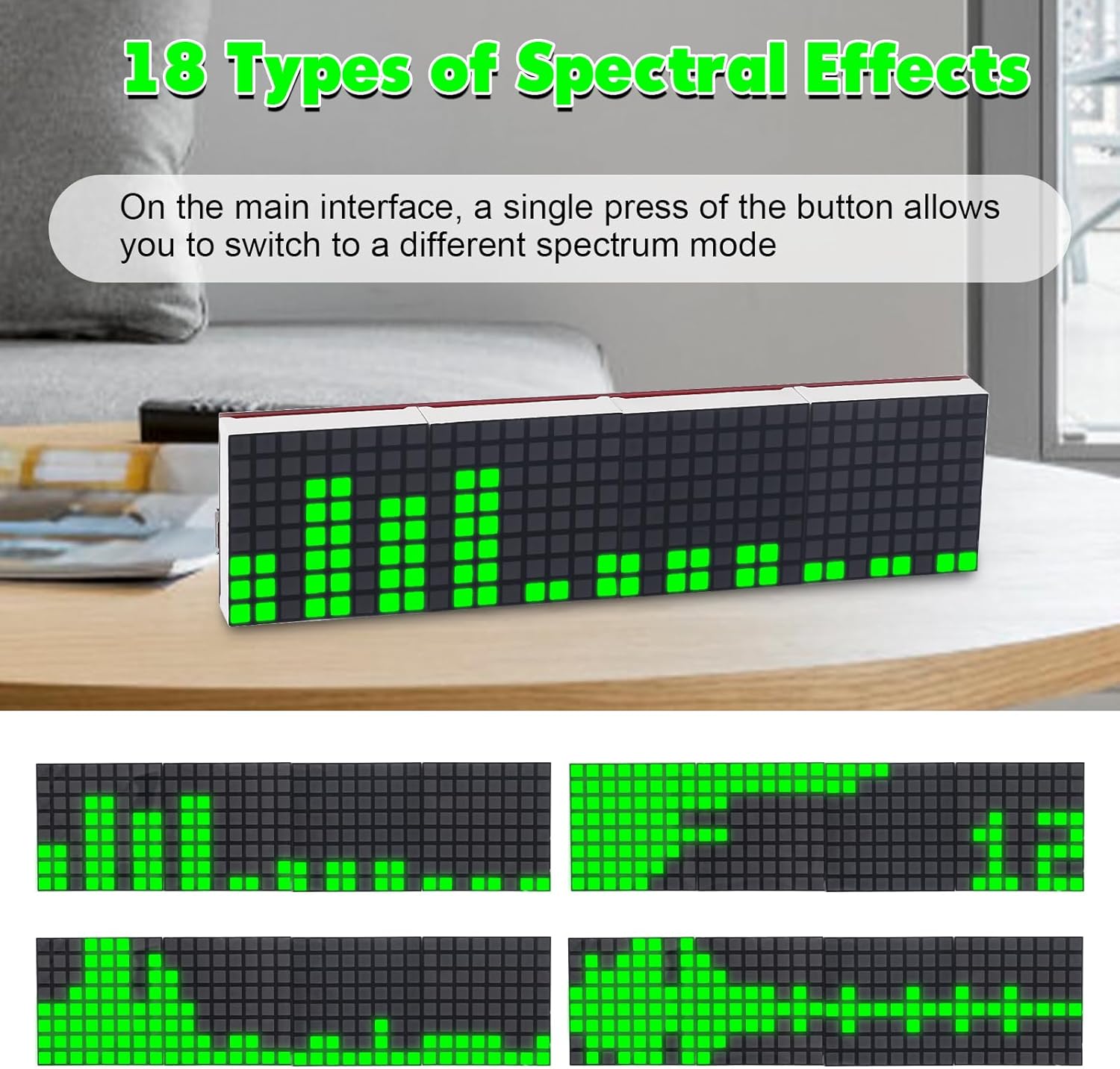
Image: A series of four images showcasing different dynamic spectral effects displayed on the PEMENOL GY21309 digital clock, illustrating the variety of visual patterns available.
6. Specifications
| Parameter | Value |
|---|---|
| Work Voltage | DC 5V |
| Display Color | Green |
| Power Type | Micro USB |
| Work Temperature | -40℃ to 85℃ |
| Work Humidity | 5% to 95% RH |
| Installed Size (L x W x H) | 128 x 32 x 18 mm (approx. 5.04 x 1.26 x 0.71 inches) |
| Material | Iron, Paper (PCB and components) |
| Display Style | Digital LED Matrix |
| Special Features | Adjustable Brightness, Night Mode, 18 Spectrum Effects |
7. Troubleshooting
- No Power/Display: Ensure the Micro USB cable is securely connected to a 5V DC power source. Check for any short circuits or unsoldered connections on the PCB, especially around the power input and main ICs.
- Incorrect Time Display: Verify the CR1220 backup battery is correctly installed and functional. Re-enter time settings as per the operating instructions.
- Spectrum Not Responding: Check the microphone module's soldering and ensure its connection to the main PCB is secure. Adjust the audio sensitivity setting.
- Partial Display/Missing Segments: Inspect the soldering of the LED matrix modules and their connections to the main PCB. Cold solder joints or bridges can cause display issues.
- Difficulty with SMD Components: If you encounter issues with tiny SMD components, consider using additional tools like a magnifying lamp, fine-tip tweezers, and a very fine soldering tip. Practice on scrap boards if available.
8. Maintenance
- Cleaning: Use a soft, dry cloth to clean the display and casing. Avoid abrasive cleaners or solvents.
- Environment: Keep the device in a dry environment, away from direct sunlight, extreme temperatures, and high humidity to ensure longevity.
- Power Source: Always use a stable 5V DC power supply to prevent damage to the electronic components.
9. Warranty and Support
For warranty information or technical support, please refer to the contact details provided in your product packaging or on the PEMENOL official website. Ensure you have your purchase details and model number (GY21309) ready when contacting support.


