1. Introduction
This manual provides essential information for the proper installation, operation, maintenance, and troubleshooting of the Secop Electronic Controller models 101N0212, 101N0340, and 101N0650. These controllers are designed for use with BD35F, BD50F, and BD35K mobile DC compressors. Please read this manual thoroughly before using the product to ensure safe and efficient operation.
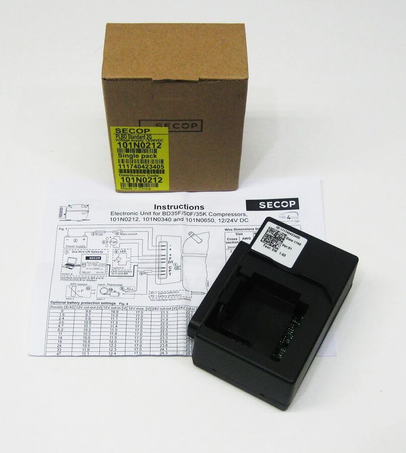
An image showing the Secop 101N0212 electronic controller, its brown cardboard packaging, and a printed instruction sheet detailing wiring diagrams and battery protection settings. The controller itself is black with a white label showing ID and version information.
2. Setup and Installation
Proper installation is crucial for the optimal performance and longevity of the electronic controller. Ensure all connections are secure and follow the wiring diagram carefully.
2.1 Power Supply Connection
The controller operates on a 12V/24V DC power supply. Connect the power supply to the designated terminals as shown in the wiring diagram (Fig. 1). Ensure correct polarity.
2.2 Wiring Diagram (Fig. 1)
Refer to the diagram below for detailed wiring instructions. This diagram illustrates connections for the power supply, fuse, main switch, fan, LED indicator, NTC sensor, and the One Wire LIN Gateway.
- Power Supply: Connect the 12V/24V DC input.
- Fuse: An appropriate fuse should be installed in the power line for protection.
- Main Switch: Connect a main switch to control power to the unit.
- Fan: Connect the compressor fan to the designated terminals.
- LED: The LED provides operational status and diagnostic feedback.
- NTC Sensor: Connect the Negative Temperature Coefficient (NTC) sensor for temperature monitoring.
- One Wire LIN Gateway: For advanced communication and control.
2.3 Wire Dimensions
The following table provides recommended wire dimensions based on cross-section and AWG for optimal performance and safety.
| Size (mm²) | AWG |
|---|---|
| 1.03 | 18 |
3. Operating Instructions
Once installed, the electronic controller manages the compressor's operation. The LED indicator provides visual feedback on the unit's status.
3.1 Optional Battery Protection Settings (Fig. 4)
The controller features optional battery protection settings to prevent excessive discharge of the battery. These settings are configured by connecting a resistor (R) of a specific value to the controller. The table below outlines the corresponding cut-out and cut-in voltages for both 12V and 24V systems.
| Resistor (R) kΩ | 12V Cut-out (V) | 12V Cut-in (V) | 12V Max (V) | 24V Cut-out (V) | 24V Cut-in (V) |
|---|---|---|---|---|---|
| 0 | 9.6 | 10.9 | 17.0 | 21.3 | 22.0 |
| 1.0 | 9.7 | 11.0 | 17.0 | 21.5 | 22.2 |
| 2.2 | 9.8 | 11.1 | 17.0 | 21.8 | 22.4 |
| 3.3 | 9.9 | 11.2 | 17.0 | 22.0 | 22.6 |
| 4.7 | 10.0 | 11.3 | 17.0 | 22.3 | 22.8 |
| 6.2 | 10.1 | 11.4 | 17.0 | 22.5 | 23.0 |
| 8.2 | 10.2 | 11.5 | 17.0 | 22.8 | 23.2 |
| 11 | 10.3 | 11.6 | 17.0 | 23.0 | 23.4 |
| 14 | 10.4 | 11.7 | 17.0 | 23.3 | 23.6 |
| 18 | 10.5 | 11.8 | 17.0 | 23.6 | 23.8 |
| 22 | 10.6 | 11.9 | 17.0 | 23.8 | 24.0 |
| 27 | 10.7 | 12.0 | 17.0 | 24.1 | 24.3 |
| 33 | 10.8 | 12.1 | 17.0 | 24.3 | 24.5 |
| 39 | 10.9 | 12.2 | 17.0 | 24.5 | 24.7 |
| 47 | 11.0 | 12.3 | 17.0 | 24.7 | 24.9 |
Note: The 12V Max column indicates the maximum voltage the 12V system can handle before potential issues. Always ensure your battery voltage remains within safe operating limits.
4. Maintenance
The Secop Electronic Controller is designed for durability and reliability. Regular maintenance is minimal but important for ensuring long-term performance.
- Cleaning: Keep the controller free from dust, dirt, and moisture. Use a soft, dry cloth for cleaning. Do not use abrasive cleaners or solvents.
- Connections: Periodically check all electrical connections to ensure they are tight and free from corrosion. Loose connections can lead to intermittent operation or damage.
- Inspection: Inspect the unit for any signs of physical damage, such as cracks or frayed wires. If damage is found, discontinue use and contact support.
5. Troubleshooting
If you encounter issues with your electronic controller, refer to the following common troubleshooting steps. For more complex problems, consult a qualified technician.
- No Power: Check the power supply connections and ensure the fuse is intact. Verify the main switch is in the 'ON' position.
- Compressor Not Running: Ensure the battery voltage is above the cut-in threshold. Check all wiring connections to the compressor and controller.
- LED Indicator: Observe the LED indicator for diagnostic codes. Consult the compressor's manual or Secop documentation for specific LED flash codes and their meanings.
- Overheating: Ensure adequate ventilation around the compressor and controller. Check the fan operation if applicable.
6. Specifications
- Product Name: Secop Electronic Controller
- Model Numbers: 101N0212, 101N0340, 101N0650
- Compatibility: BD35F, BD50F, BD35K Mobile DC Compressors
- Voltage: 12V/24V DC
- Manufacturer: ALoEu
- ASIN: B0CS7CSWM6
7. Warranty and Support
For information regarding product warranty, please refer to the warranty card included with your purchase or contact the seller directly. For technical support or service inquiries, please reach out to the manufacturer or authorized service centers.