1. Introduction
The FNIRSI LCR-TC1 is a versatile multi-functional tester designed for electronic components. It features a colorful TFT backlight display and can be widely used to detect and analyze various components including NPN and PNP transistors, capacitors, resistors, diodes, triodes, N-channel and P-channel MOSFETs, IGBTs, JFETs, triacs, and batteries. It also includes functionality for detecting infrared waveforms and Zener diodes, along with a self-calibration feature.
This manual provides detailed instructions for the proper setup, operation, and maintenance of your LCR-TC1 tester.
2. Package Contents
Upon opening the package, please verify that all the following items are included:
- FNIRSI LCR-TC1 Multi-functional Transistor Tester Unit
- Micro USB Charging Cable
- Test Hooks (Red, Green, Black)
- Assorted Test Components (e.g., capacitor, resistor, diode for initial testing)
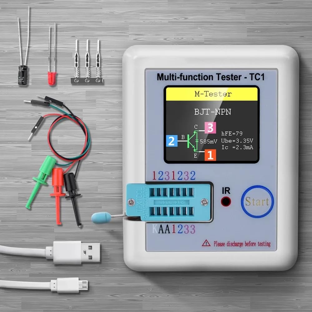
Figure 2.1: The FNIRSI LCR-TC1 tester shown with its standard accessories, including the main unit, test leads with clips, and a USB charging cable. Various small electronic components are also visible, demonstrating the types of items the device can test.
3. Product Overview
The LCR-TC1 features a compact design with a 1.8-inch TFT color display for clear result visualization. It includes a ZIF (Zero Insertion Force) socket for easy component insertion and dedicated test points for external connections using test hooks.
Key Features:
- 1.8-inch TFT Color Display
- One-button Operation for automatic detection
- Built-in Rechargeable Lithium Battery
- IR Decoder for infrared waveform analysis
- Self-calibration function

Figure 3.1: Side view of the FNIRSI LCR-TC1 tester, illustrating its compact dimensions: approximately 91mm in length, 69mm in width, and 28mm in height. The image also shows the ZIF socket and the 'Start' button.
4. Getting Started (Setup)
4.1 Charging the Battery
The LCR-TC1 is powered by a built-in rechargeable lithium battery. Before first use, or if the battery is low, connect the provided Micro USB cable to the device's charging port and to a standard USB power adapter (not included). The charging indicator will show the charging status.
4.2 Initial Power On and Self-Calibration
To power on the device, press the "Start" button. The device will perform a brief self-test. For accurate measurements, it is recommended to perform a self-calibration periodically or if you notice inconsistent readings.
- Ensure no components are inserted into the ZIF socket or connected to the test points.
- Press and hold the "Start" button for a few seconds until "Self-test mode" or similar message appears.
- Follow the on-screen prompts, which may instruct you to short the test pins (1-2-3) together.
- Once calibration is complete, the device will return to the main testing interface.
5. Component Testing (Operating Instructions)
5.1 Safety Precaution: Discharge Components
WARNING: Before testing any capacitor or other component that may store an electrical charge, ensure it is fully discharged. Failure to do so can damage the tester and pose a safety risk. Large capacitors, especially, must be discharged through a suitable resistor before connecting to the tester.

Figure 5.1: The FNIRSI LCR-TC1 tester displaying a warning message to discharge electronics before testing. This emphasizes the critical safety step to prevent damage to the device and ensure accurate readings.
5.2 General Testing Procedure
The LCR-TC1 operates with a simple one-button process for most component tests:
- Prepare Component: Ensure the component is clean and its leads are straight. If testing a charged component, discharge it first (refer to Section 5.1).
- Connect Component: Insert the component's pins into the corresponding holes of the ZIF socket (pins 1, 2, 3) or connect the test hooks to the external test points. The tester automatically identifies the pinout.
- Initiate Test: Press the "Start" button. The tester will automatically detect the component type and display its parameters on the TFT screen.
- Read Results: The screen will show the component type, its measured values (e.g., capacitance, resistance, inductance, voltage drop), and often a graphical representation of its pinout.
5.3 Specific Component Examples
5.3.1 Transistor Testing (NPN/PNP, MOSFET, JFET, IGBT)
Insert the transistor's leads into the ZIF socket or connect via test hooks. The tester will identify the transistor type (NPN, PNP, MOSFET, JFET, IGBT), its pinout (Emitter, Base, Collector or Gate, Drain, Source), and parameters like hFE (for BJTs), Vgs (for MOSFETs), and capacitance.

Figure 5.2: The FNIRSI LCR-TC1 tester actively measuring a transistor connected via external test leads. The screen displays the component type (N-E-MOS), its pin configuration (G, D, S), and measured parameters such as threshold voltage (Vt) and capacitance (Cgs).
5.3.2 Capacitor Testing
Connect the capacitor leads to any two or three test points. The tester will measure capacitance (25pF-100mF) and Equivalent Series Resistance (ESR). It will also indicate the voltage loss (Vloss) for electrolytic capacitors.

Figure 5.3: The FNIRSI LCR-TC1 tester displaying the results of a capacitor test. The screen shows the component identified as a "Capacitor," along with its measured capacitance (988.1nF), ESR (Equivalent Series Resistance) of 4.5Ω, and Vloss (voltage loss) of 0.5%.
5.3.3 Resistor Testing
Connect the resistor leads to any two test points. The tester will measure resistance (0.01Ω-50MΩ). If three leads are connected, it can also detect potentiometers and measure their resistance values.

Figure 5.4: The FNIRSI LCR-TC1 tester displaying the measurement of a resistor. The screen clearly indicates "Resistor" and its measured value, in this case, 2000Ω. The image also shows the ZIF socket and external test leads.
5.3.4 Diode and Zener Diode Testing
Connect the diode leads. The tester will identify the anode and cathode, and measure the forward voltage drop. For Zener diodes, it can detect and measure Zener voltage within the range of 0.01V-30V.
5.3.5 Inductor Testing
Connect the inductor leads. The tester will measure inductance (0.01mH-20H) and its DC resistance.
5.3.6 Infrared (IR) Decoding
To test an infrared remote control, align its IR emitter with the "IR" light sensor on the tester. Press a button on the remote control. If successfully decoded, the tester will display the data code and the infrared waveform on the screen.
6. Specifications
The following table outlines the technical specifications of the FNIRSI LCR-TC1 Multi-functional Transistor Tester:
Figure 6.1: A detailed table presenting the technical specifications of the FNIRSI LCR-TC1, including display type, measurement ranges for various components, battery information, and physical dimensions.
| Parameter | Value |
|---|---|
| Display | 1.8-inch TFT Screen |
| Diode Range | <4.5V |
| Zener Diode Detect Area (Transistor) | 0.01-4.5V |
| Zener Diode Detect Area (Zener) | 0.01-30V |
| Triac Range | IGT <6mA |
| Capacitance | 25pF-100mF |
| Resistance | 0.01-50MΩ |
| Inductance | 0.01mH-20H |
| Battery Test Range | 0.1-4.5V |
| Power Mode | Rechargeable Lithium Battery (INCLUDED) |
| Item Size | 8.8 x 8 x 2.8 cm / 3.47 x 3.15 x 1.10 in |
| Item Weight | 111.5 g / 3.94 oz |
| Package Size | 14.5 x 12 x 2.7 cm / 5.71 x 4.73 x 1.06 in |
| Package Weight | 114 g / 4.02 oz |
| Operating Voltage (Min.) | 4.5 Volts |
| Certifications | CE, RoHS |
7. Troubleshooting
Common Issues and Solutions:
- "Please discharge before testing" message: This warning indicates that the component you are attempting to test may hold an electrical charge, particularly capacitors. Always ensure components are fully discharged before connecting them to the tester to prevent damage. Use a suitable discharge resistor for large capacitors.
- Inaccurate or inconsistent readings:
- Ensure the component leads are clean and make good contact with the ZIF socket or test hooks.
- Perform a self-calibration (refer to Section 4.2).
- Check the battery level; a low battery can affect measurement accuracy. Recharge if necessary.
- Device does not power on:
- Ensure the battery is sufficiently charged. Connect the USB cable and allow it to charge for some time.
- Verify the USB cable and power adapter are functioning correctly.
8. Care and Maintenance
- Cleaning: Use a soft, dry cloth to clean the device. Do not use abrasive cleaners or solvents.
- Storage: Store the tester in a cool, dry place, away from direct sunlight and extreme temperatures.
- Battery Care: For optimal battery life, avoid fully discharging the battery frequently. If storing for extended periods, charge the battery to approximately 50% every few months.
- Component Handling: Always handle components carefully, especially when inserting them into the ZIF socket, to avoid bending or damaging the pins.
9. Warranty and Support
For warranty information and technical support, please refer to the documentation provided with your purchase or contact the manufacturer directly. Keep your proof of purchase for warranty claims.
Manufacturer: FNIRSI
For further assistance, please visit the official FNIRSI website or contact their customer support.


