1. Introduction
The waveshare 4-Ch RS485 to RJ45 Ethernet Serial Server, Model 4-CH RS485 TO POE ETH (B), is a multi-functional industrial device designed for data acquisition and IoT gateway applications. It features four independent RS485 channels, allowing for effective and isolated data transmission. This module integrates functionalities such as a serial server, Modbus gateway, MQTT gateway, and RS485 to JSON conversion, making it suitable for diverse industrial network environments. Its robust design includes power supply and signal isolation, along with comprehensive protection features, ensuring stable and reliable operation.
Video 1: Overview of the waveshare 4-Ch RS485 to RJ45 Ethernet Serial Server. This video demonstrates the device's key features and applications, highlighting its multi-functional capabilities and robust design for industrial use.
2. Package Contents
Upon unpacking, please verify that all the following items are included:
- 1x 4-CH RS485 TO POE ETH (B) Module
- 1x Rail-mount buckle
- 1x Screwdriver
- 1x Screws pack (4 screws)

Image 1: Illustration of the waveshare 4-Ch RS485 to RJ45 Ethernet Serial Server and its included accessories, such as the rail-mount buckle, screwdriver, and screws.
3. Features at a Glance
The 4-Ch RS485 to RJ45 Ethernet Serial Server offers a comprehensive set of features for industrial communication needs:
- Independent RS485 Channels: Four RS485 channels operate independently, ensuring efficient and isolated data transmission without mutual interference.
- Multi-functional Integration: Combines serial server, Modbus gateway, MQTT gateway, and RS485 to JSON functionalities.
- Stable Power Input: Utilizes a screw terminal for reliable and stable power connection.
- Flexible Mounting: Supports both wall-mount and rail-mount installations for quick deployment and expansion in industrial settings.
- Industrial Isolation: Features power isolation and signal isolation for enhanced reliability and anti-interference.
- PoE Ethernet Port: Includes a Power over Ethernet (PoE) enabled RJ45 port for simplified power and data connectivity (PoE version only).
- Multi-Host Support: Designed to prevent crosstalk while communicating with multiple network devices.
- Configurable: Supports web browser configuration, DHCP, DNS, and device management functions library.

Image 2: Visual representation of the core features, including industrial isolation, rail-mount capability, Modbus gateway, 4-channel independent RS485, and multiple power supply methods.
4. Specifications
Detailed technical specifications for the 4-CH RS485 TO POE ETH (B) module:
| Category | Specification |
|---|---|
| Product Type | Serial server, Modbus Gateway, MQTT Gateway |
| Basic Function | Bi-directional transparent data transmission between RS485 and Ethernet |
| Communication Interface | RS485 port x 4, Ethernet port x 1 |
| Power Supply | DC 6 - 45V screw terminal, or PoE port |
| Isolation Protection | Power isolation, Signal isolation |
| Ethernet | RJ45 10 / 100M auto-negotiation, 2 KV surge protection, IEEE 802.3af compliant (PoE) |
| Serial Port | Isolated RS485 (4 channels can receive and transmit independently) |
| Baudrate | 300 - 115200 bps |
| Parity Bit | None, odd, even, mark, space |
| Data Bit | 5 - 9 bits |
| Flow Control | N/A |
| Protocol | ETHERNET, IP, TCP, UDP, HTTP, ARP, ICMP, DHCP, DNS |
| Configuration | Host, web browser, device management functions library |
| Communication Method | TCP/IP direct communication, VCOM |
| Operating Mode | TCP server, TCP client (coexisting with TCP server), UDP, UDP multicast |
| Operating Temperature | -40°C ~ 85°C |
| Humidity Range | 5% - 95% relative humidity |
| Dimensions | L × W × H: 91.0 × 64.5 × 24.2 mm |
| Item Weight | 7.4 ounces |

Image 3: A comprehensive table outlining the technical specifications and version options for the waveshare 4-Ch RS485 to RJ45 Ethernet Serial Server.
5. Setup
Follow these steps to set up your waveshare 4-Ch RS485 to RJ45 Ethernet Serial Server:
5.1. Power Connection
- DC Power Input: Connect a DC 6-45V power supply to the V+ and V- screw terminals. Ensure correct polarity.
- PoE (Power over Ethernet): If using the PoE version, connect a PoE-enabled Ethernet cable to the RJ45 port. This will provide both power and data connectivity.
5.2. Network Connection
- Connect a standard RJ45 Ethernet cable from your network switch or router to the Ethernet port on the module.
- The module defaults to static IP addresses in the range of 192.168.1.200-192.168.1.204. It is recommended to initially set up the device on an isolated network to avoid IP conflicts.
5.3. RS485 Device Connection
- Connect your RS485 devices to the corresponding A+, B-, and Signal Ground terminals for each of the four RS485 channels.
- Ensure correct wiring polarity (A+ to A+, B- to B-) for proper communication.
5.4. Initial Configuration
- Access the device's configuration interface via a web browser by entering its default IP address (e.g., 192.168.1.200).
- Alternatively, use the provided VirCom software (available from the Waveshare Wiki) to discover and configure the device on your network.
- You can change the IP settings to DHCP or assign a static IP within your network range.

Image 4: Diagram illustrating the primary function of bi-directional data transmission, multi-power supply options (PoE and screw terminal), and the industrial rail-mount design.
6. Operating Instructions
The 4-Ch RS485 to RJ45 Ethernet Serial Server supports various operating modes and protocols:
6.1. Multi Communication Modes
- TCP Server: Supports up to 30 concurrent TCP connections. The module listens on configured ports, and data from serial devices is transferred to connected TCP clients.
- TCP Client: Allows concurrent connection to up to 7 target IPs. It can also function as a server simultaneously, supporting 22 concurrent client connections. It establishes bi-directional transparent transfer between the server and serial device.
- UDP Multicast: In UDP multicast mode, the module sends and receives data to and from a multicast group, reducing network load.
- UDP Mode: The module communicates with specific IP and port numbers, improving data transfer accuracy.
6.2. Modbus Gateway Support
The module functions as a Modbus gateway, facilitating communication between Modbus TCP and Modbus RTU devices. This is ideal for upgrading Modbus networking infrastructure.
6.3. MQTT/JSON to Modbus Conversion
When used as an MQTT gateway, the device can upload serial data to an MQTT server via transparent transmission. It supports various cloud platforms. Acquired Modbus RTU or non-standard serial data can be parsed into JSON format and packaged into MQTT data packets for uploading. As a JSON data acquisition gateway, it can connect to data acquisition instruments via RS485, acquire data, convert it to JSON, and post it to a server. The uploaded data format can be configured via host, and the JSON upload protocol can be MQTT, HTTP POST, HTTP GET, etc.
6.4. Multi Hosts Roll-Polling Support
This feature ensures that different network devices are identified and responded to respectively, preventing crosstalk when communicating with multiple network devices.
6.5. User-Defined Heartbeat/Registration Packet
Facilitates easy cloud communication and device identification through user-defined heartbeat and registration packets.
6.6. NTP Protocol Support
Supports Network Time Protocol (NTP) for obtaining network time information or for data upload synchronization.
6.7. Multi Configuration Methods
The module can be configured using various methods, including a web browser interface, obtaining dynamic IP via DHCP, and DNS protocol connected domain server address. A device management functions library is also available.

Image 5: Visual overview of advanced features such as MQTT/JSON to Modbus conversion, multi-host roll-polling, NTP protocol support, and various configuration methods.
7. Interface Introduction
Understanding the physical interfaces and indicators is crucial for proper operation:
7.1. Physical Interfaces
- RST Button: Used to reset the device to factory default settings.
- DC 6-45V Power Input: Screw terminals for connecting external DC power (V+, V-).
- RS485 Ports (1-4): Each port has A+, B-, and Signal Ground terminals for connecting RS485 devices.
- PoE ETH Port: RJ45 connector for Ethernet and Power over Ethernet (PoE) input.
7.2. Indicator Description
- PWR (Power Indicator): Illuminates when the device is powered on.
- NET (Network Indicator): Blinks when connected to the Ethernet network.
- LINKx (Link Indicator): Lights up when a connection is established on the corresponding RS485 channel (x=1, 2, 3, 4).
- ACTx (Activity Indicator): Lights up when data is being transmitted on the corresponding RS485 channel (x=1, 2, 3, 4).
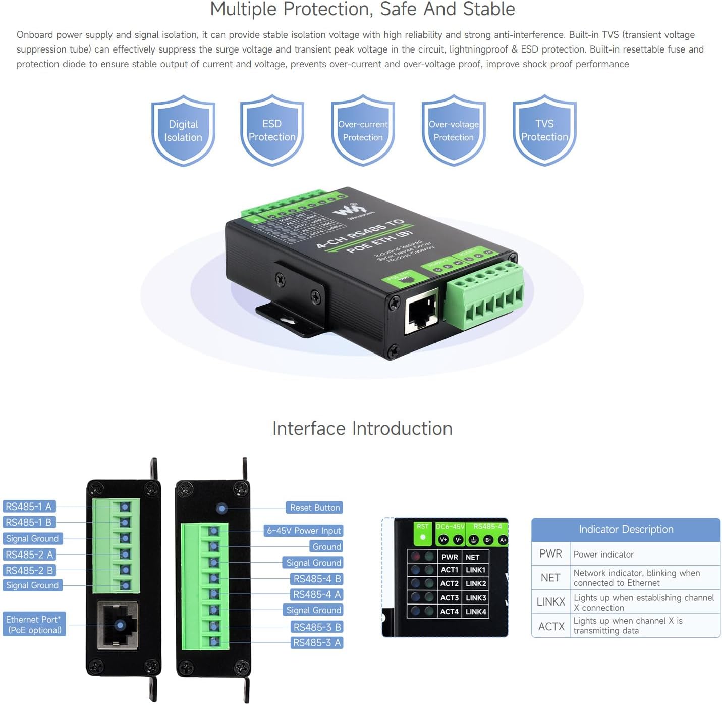
Image 6: Detailed view of the device's interfaces, including the reset button, power input, RS485 terminals, Ethernet port, and a description of the LED indicators (PWR, NET, LINKx, ACTx).
8. Multiple Protection, Safe And Stable
The module is designed with multiple protection mechanisms to ensure high reliability and strong anti-interference capabilities:
- Digital Isolation: Provides isolation for digital signals.
- ESD Protection: Electrostatic Discharge protection.
- Over-current Protection: Safeguards against excessive current.
- Over-voltage Protection: Protects against voltage spikes.
- TVS Protection: Built-in Transient Voltage Suppression (TVS) tube effectively suppresses surge voltage and transient peak voltage in the circuit.
- Resettable Fuse & Protection Diode: Ensures stable output of current and voltage, preventing over-current and over-voltage, and improving shock-proof performance.
9. Aluminium Alloy Enclosure
The device features a durable aluminum alloy enclosure with sandblasting and anodic oxidation treatment. This robust construction provides solid protection, a good hand feeling, and supports both wall-mount and rail-mount installations for industrial environments.
10. Outline Dimensions
The physical dimensions of the module are as follows:
- Length (L): 91.0 mm
- Width (W): 64.5 mm
- Height (H): 24.2 mm

Image 7: Diagram showing the precise outline dimensions of the module in millimeters, along with information on batch customization support.
11. Maintenance
To ensure the longevity and optimal performance of your waveshare 4-Ch RS485 to RJ45 Ethernet Serial Server, consider the following maintenance guidelines:
- Regular Inspection: Periodically check all cable connections (power, Ethernet, RS485) to ensure they are secure and free from damage.
- Environmental Control: Operate the device within the specified operating temperature (-40°C ~ 85°C) and humidity (5% - 95% relative humidity) ranges. Avoid exposure to extreme conditions, dust, and moisture.
- Cleaning: Keep the device clean and free from dust accumulation. Use a soft, dry cloth for cleaning. Do not use liquid cleaners.
- Firmware Updates: Check the official Waveshare website or Wiki periodically for any available firmware updates. Applying updates can improve performance, add features, or fix bugs.
- Power Cycling: If the device becomes unresponsive, perform a power cycle (disconnect and reconnect power) as a first troubleshooting step.
12. Troubleshooting
This section addresses common issues you might encounter with the waveshare 4-Ch RS485 to RJ45 Ethernet Serial Server:
12.1. No Power / Power LED Off
- Check Power Supply: Ensure the DC 6-45V power supply is correctly connected to the screw terminals and is providing the correct voltage.
- Check PoE: If using PoE, verify that the Ethernet cable is connected to a PoE-enabled port on your switch/injector and that the PoE source is active.
- Inspect Wiring: Confirm that the power wires are securely fastened in the screw terminals and that there are no shorts or breaks.
12.2. No Network Connectivity / NET LED Not Blinking
- Ethernet Cable: Ensure the RJ45 Ethernet cable is securely connected to both the module and your network device. Try a different cable.
- Network Configuration: The device defaults to static IPs (192.168.1.200-192.168.1.204). Ensure your PC is on the same subnet (e.g., 192.168.1.x) to access the web interface or use the VirCom software.
- IP Conflicts: If other devices on your network use the default IPs, configure the module on an isolated network first, then change its IP settings.
- DHCP Settings: If configured for DHCP, ensure a DHCP server is available on your network.
12.3. RS485 Communication Failure / ACTx LED Not Blinking
- Wiring: Double-check the RS485 wiring (A+ to A+, B- to B-) between the module and your serial devices. Ensure Signal Ground is also connected if required.
- Serial Parameters: Verify that the baud rate, parity bit, and data bit settings on the module match those of your connected RS485 devices.
- Device Addressing: For Modbus or other protocols, ensure correct device addressing and commands are being used.
- Isolation: While the module provides isolation, ensure external RS485 devices are also properly isolated or grounded to prevent ground loops.
12.4. Cannot Access Configuration Interface
- Default IP: Confirm you are using the correct default IP address (e.g., 192.168.1.200) or the IP you previously assigned.
- Network Connection: Ensure your PC is on the same subnet as the module.
- VirCom Software: Use the Waveshare VirCom software to discover the device's IP address if it's unknown.
- Firewall: Temporarily disable your computer's firewall to rule out blocking access.
- Reset: If all else fails, press the RST button to restore factory default settings (this will reset the IP to default).
For more detailed troubleshooting and advanced configurations, please refer to the official Waveshare Wiki for the 4-CH RS485 TO POE ETH (B) module.
13. Warranty and Support
This waveshare product is designed for reliability and performance. For specific warranty terms and conditions, please refer to the purchase documentation or contact your vendor. Waveshare provides technical support and resources to assist with product usage and troubleshooting.
13.1. Technical Support
For technical assistance, detailed documentation, and software downloads, please visit the official Waveshare website or their product Wiki. The Wiki often contains comprehensive guides, examples, and FAQs that can help resolve complex issues.
13.2. Contact Information
You can typically find contact information for Waveshare support on their official website. Please have your product model (4-CH RS485 TO POE ETH (B)) and any relevant purchase details ready when seeking support.


