1. Introduction
The NOYAFA NF-827 Circuit Breaker Finder Tool Kit is a versatile electrical testing device designed for efficient and accurate identification of circuit breakers, GFCI outlet testing, and non-contact voltage detection. This manual provides detailed instructions for the safe and effective use of your NF-827 kit.
2. Safety Information
WARNING: Always exercise extreme caution when working with electricity. Failure to follow these safety guidelines may result in electric shock, fire, or personal injury.
- Do not use the device if it appears damaged or is not functioning properly.
- Ensure the power source is within the specified operating voltage range (90-120V AC for the transmitter).
- Do not open the device casing. Refer all servicing to qualified personnel.
- Always wear appropriate personal protective equipment (PPE), such as insulated gloves and safety glasses, when working with electrical circuits.
- Before testing, verify that the circuit is de-energized if you intend to work on it.
- Keep the device dry and clean. Do not expose it to moisture or extreme temperatures.
3. Package Contents
Verify that all items are present in your NOYAFA NF-827 kit:
- NF-827 Receiver Unit
- NF-827 Transmitter Unit (Socket Tester)
- 2-Prong Adapter
- E26 Light Socket Adapter
- Alligator Clip Adapter Cable
- Carrying Bag
- User Manual (this document)
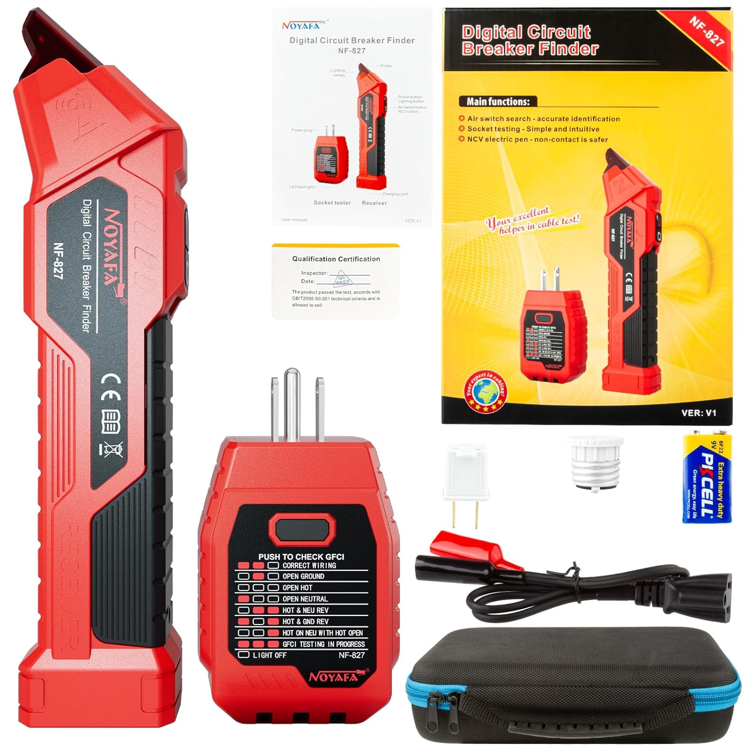
Figure 3.1: Complete NOYAFA NF-827 Kit Contents.
This image displays all components included in the NOYAFA NF-827 Circuit Breaker Finder Tool Kit. It features the red receiver unit, the red transmitter (socket tester) with its three-prong plug, a white two-prong adapter, a white light socket adapter, a black cable with red and black alligator clips, and a black zippered carrying case with blue trim.
4. Product Overview
The NF-827 consists of two main parts: the Receiver and the Transmitter (Socket Tester).
4.1 Receiver Unit
The receiver is a handheld device used to detect the signal from the transmitter at the circuit breaker panel. It features a power button, a signal strength indicator, and an LED light at the tip for visual feedback.

Figure 4.1: Receiver Unit Operation Indicators.
This image illustrates the visual indicators on the receiver unit. When the device is powered on, a red light illuminates. As the receiver approaches the target circuit breaker, the light changes to purple and its brightness, along with the beep frequency, increases, indicating proximity to the correct breaker.
4.2 Transmitter Unit (Socket Tester)
The transmitter plugs into an electrical outlet and sends a signal through the circuit. It also functions as a GFCI outlet tester and provides wiring status indications via LED lights.
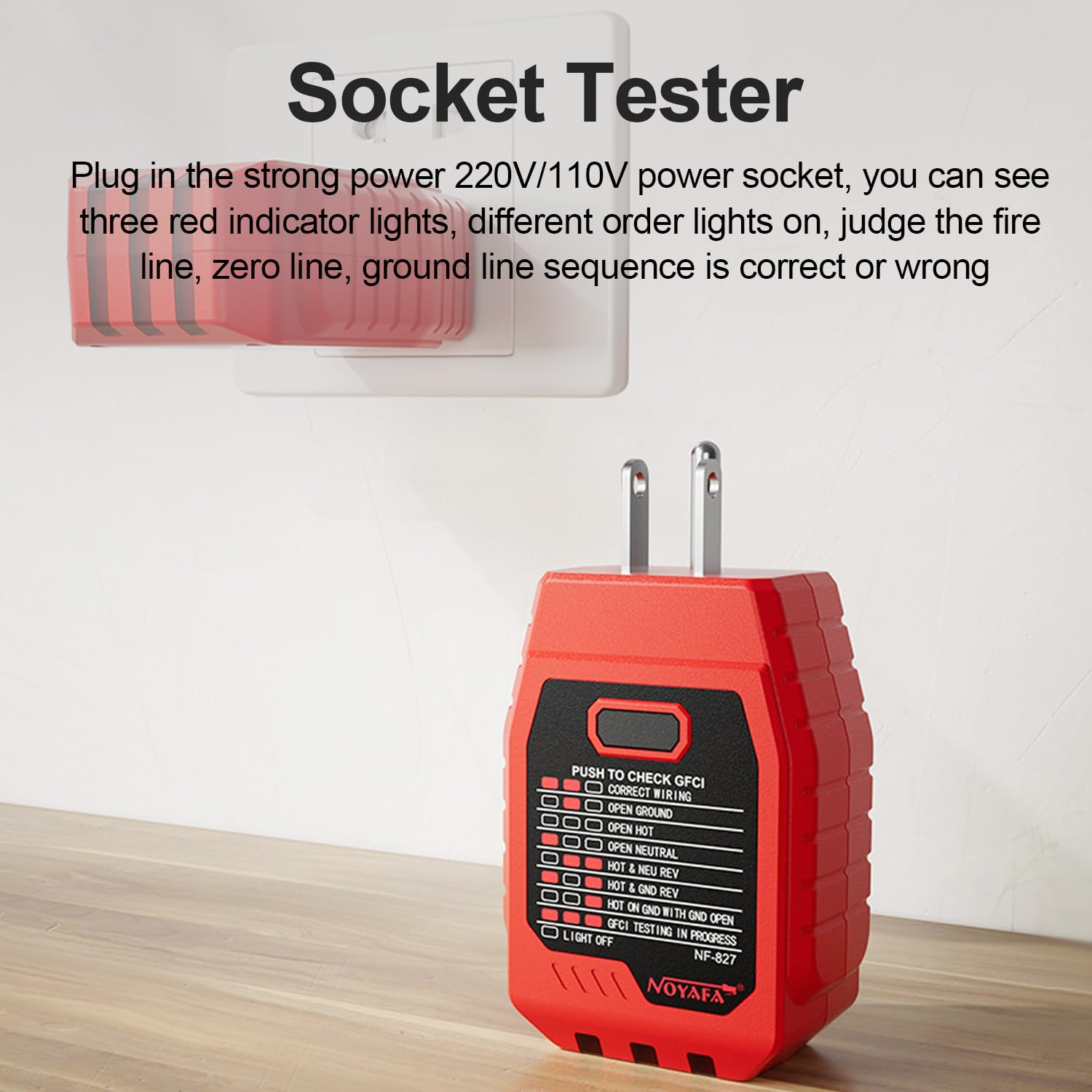
Figure 4.2: Transmitter Unit (Socket Tester) Features.
This image shows the NOYAFA NF-827 Socket Tester plugged into a wall outlet. The tester features three red indicator lights that illuminate in various combinations to show the correct or incorrect wiring sequence of the live, neutral, and ground lines. It also includes a button for GFCI testing.
4.3 2-in-1 Convenient Design
The transmitter can be conveniently docked into the receiver unit for compact storage and easy transport when not in use.

Figure 4.3: 2-in-1 Docking Feature.
This image demonstrates the integrated design of the NF-827, where the transmitter unit can be securely docked into the receiver unit. This feature allows for convenient storage and portability, keeping both components together when not in active use.
5. Setup
Before first use, ensure the battery is installed in the receiver unit. The NF-827 receiver typically uses a 9V battery (often included). Open the battery compartment on the back of the receiver and insert the battery, observing polarity.
6. Operating Instructions
6.1 Circuit Breaker Identification
This function helps you quickly and accurately find the correct circuit breaker for a specific outlet or fixture.
- Plug in the Transmitter: Insert the NF-827 Transmitter (Socket Tester) into the electrical outlet you wish to identify. Ensure the outlet is live (powered). If using a 2-prong outlet, attach the 2-prong adapter first. For light fixtures, use the E26 light socket adapter. For bare wires, use the alligator clip adapter cable, ensuring proper connection to live and neutral/ground wires.
- Activate the Receiver: Long press the power button on the Receiver unit for approximately 1 second to turn it on. The probe light will illuminate red, indicating it is in line finding mode.
- Scan the Breaker Panel: Go to your electrical service panel. Slowly move the tip of the Receiver unit along the circuit breakers.
- Identify the Breaker: As you approach the correct circuit breaker, the Receiver will emit a continuous, rapid beeping sound, and the probe light will turn purple and become brighter. The breaker with the fastest beep frequency and brightest purple light is the target circuit breaker.
- Verify: To confirm, flip the identified breaker to the OFF position. The power to the tested outlet should now be off. If it is, you have successfully identified the breaker.
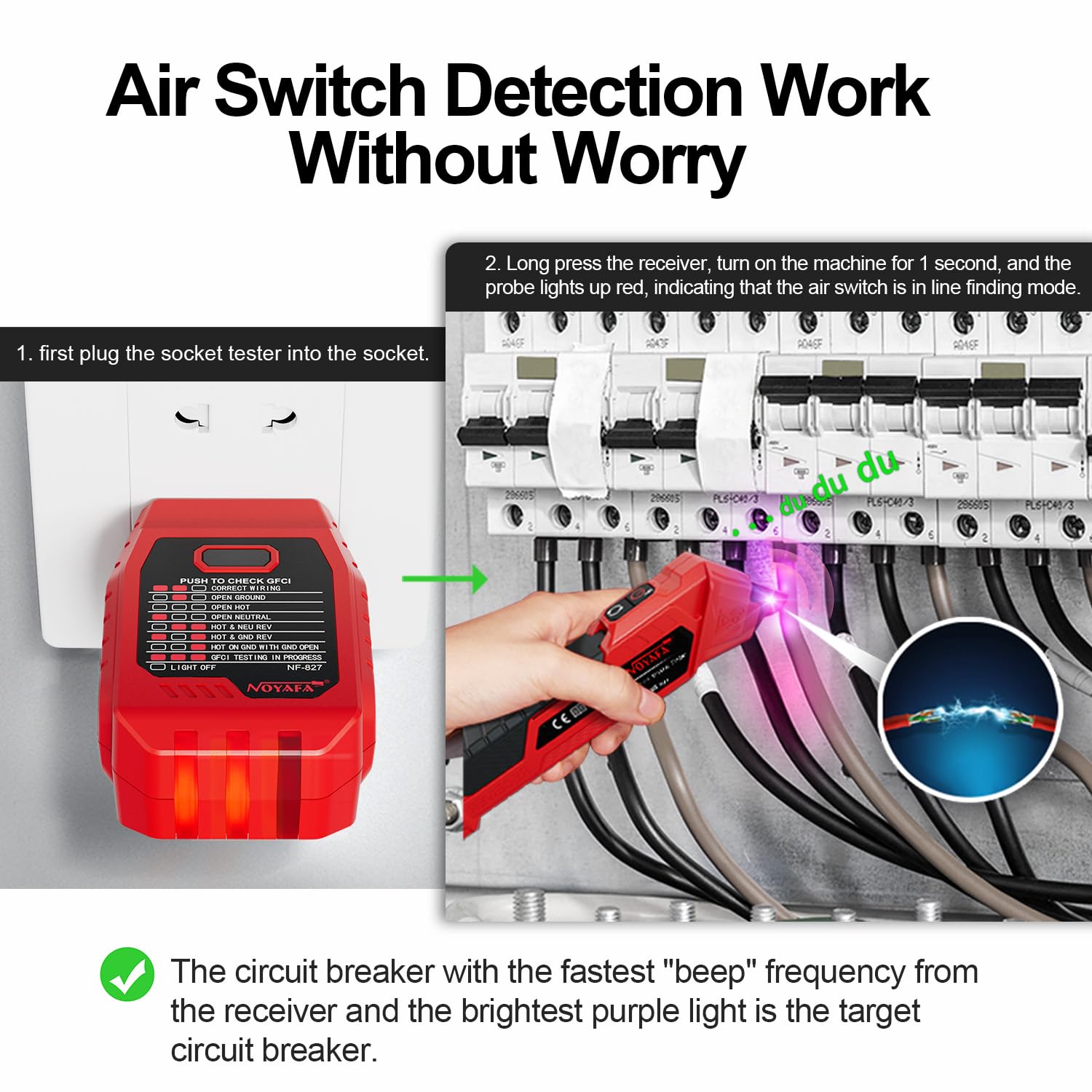
Figure 6.1: Circuit Breaker Identification Process.
This diagram illustrates the two-step process for identifying a circuit breaker. First, the socket tester (transmitter) is plugged into the desired outlet. Second, the receiver unit is used to scan the circuit breakers in the electrical panel. The receiver provides audible and visual cues (beeping and purple light) to indicate the correct breaker.

Figure 6.2: Accurate Circuit Breaker Identification.
This image focuses on the receiver unit as it is used to accurately identify a circuit breaker. The purple light emanating from the tip of the receiver signifies that it has located the correct breaker, ensuring efficient electrical troubleshooting.
6.2 GFCI Outlet Testing
The Transmitter unit includes an integrated GFCI (Ground Fault Circuit Interrupter) outlet tester.
- Plug in the Transmitter: Insert the Transmitter into a GFCI outlet.
- Check Wiring Status: Observe the LED indicators on the Transmitter. They will show the current wiring status (e.g., Correct Wiring, Open Ground, Open Neutral, etc.). Refer to the legend on the Transmitter for interpretation.
- Perform GFCI Test: Press the "PUSH TO CHECK GFCI" button on the Transmitter. A properly functioning GFCI outlet should trip (turn off) immediately.
- Reset GFCI: If the GFCI trips, press the reset button on the GFCI outlet to restore power. If it does not trip, the GFCI outlet may be faulty and should be inspected by a qualified electrician.
6.3 Non-Contact Voltage (NCV) Detection
The Receiver unit can also function as a non-contact voltage detector.
- Turn on Receiver: Power on the Receiver unit.
- Detect Voltage: Place the tip of the Receiver near an AC voltage source (e.g., a live wire, outlet, or light switch). The Receiver will beep and the light will flash if AC voltage is detected, indicating the presence of live current.
7. Maintenance
- Cleaning: Wipe the device with a dry, clean cloth. Do not use abrasive cleaners or solvents.
- Storage: Store the kit in its carrying bag in a cool, dry place, away from direct sunlight and extreme temperatures.
- Battery Replacement: Replace the 9V battery in the Receiver unit when the low battery indicator appears or when the device performance degrades.
8. Troubleshooting
| Problem | Possible Cause | Solution |
|---|---|---|
| Receiver does not turn on. | Dead or improperly installed battery. | Check battery polarity or replace with a new 9V battery. |
| Cannot find the correct breaker. | Transmitter not plugged in correctly or outlet is not live. Scanning too fast. Interference from other circuits. | Ensure transmitter is securely plugged into a live outlet. Scan the breakers slowly and deliberately. Try testing from a different outlet on the same circuit if possible. Ensure the receiver tip is close to each breaker. |
| GFCI test button does not trip the outlet. | GFCI outlet is faulty. Outlet is not a GFCI type. | Have the GFCI outlet inspected and repaired by a qualified electrician. Confirm the outlet is indeed a GFCI outlet. |
| Inaccurate NCV readings. | Too much distance from voltage source. Strong electromagnetic interference. | Ensure the tip of the receiver is very close to the suspected live wire/component. Move away from sources of strong electromagnetic fields. |
9. Specifications
- Model: NF-827
- Brand: NOYAFA
- Power Source: Corded Electric (Transmitter), Battery (Receiver)
- Min. Operating Voltage: 90 Volts AC
- Color: Red
- Item Weight: Approximately 1.37 pounds (total kit)
- Package Dimensions: Approximately 9.72 x 6.77 x 2.6 inches
- Measurement Type: Voltmeter (for NCV and GFCI functions)
10. Warranty and Support
For warranty information and technical support, please refer to the official NOYAFA website or contact their customer service directly. Keep your purchase receipt as proof of purchase for any warranty claims.
For more information, visit the NOYAFA Store on Amazon.


