
1. Introduction
This manual provides essential information for the safe and efficient operation, installation, and maintenance of your JOCCOS 5.5Kw 6000 RPM Large Servo Motor and 380V Driver. Please read this manual thoroughly before using the product to ensure correct usage and to prevent damage or injury. This system is designed for applications such as pressure machines, injection molding machines, machining centers, and engraving machines.
2. Package Contents
Verify that all components listed below are included in your package. If any items are missing or damaged, please contact your supplier immediately.
- 1x Servo Motor
- 1x 380V Driver
- 1x 3M Encoder Wire
- 1x 3 Meter Power Line
- 1x Plug
- 1x Resistance 1000W-50RJ
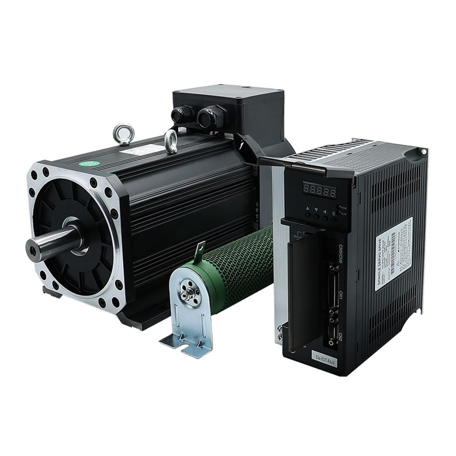
Figure 2.1: Complete JOCCOS Servo Motor and Driver Kit, including motor, driver, cables, and resistance.
3. Setup and Installation
Proper installation is crucial for the performance and longevity of the servo system. Ensure all power is disconnected before beginning installation.
3.1 Motor Installation
Mount the servo motor securely to a stable, vibration-free surface. Ensure adequate ventilation around the motor to prevent overheating. Connect the motor power lines (U, V, W) and the PE (protective earth) to the corresponding terminals on the driver.

Figure 3.1: JOCCOS Servo Motor. Ensure secure mounting and proper ventilation.
3.2 Driver Installation
Install the 380V driver in a clean, dry environment with sufficient space for heat dissipation. Connect the main power supply (R, S, T, PE) to the driver's input terminals. Connect the 3M encoder wire from the motor to the CN1 or CN2 port on the driver, ensuring correct pin alignment.

Figure 3.2: Front panel of the JOCCOS 380V Servo Driver, showing power and motor connection terminals.

Figure 3.3: Side view of the JOCCOS 380V Servo Driver, highlighting cooling fins and overall compact design.
3.3 Resistance Connection
Connect the 1000W-50RJ resistance to the designated terminals on the driver (P and BK). This resistance is crucial for dissipating regenerative energy during deceleration, protecting the driver from overvoltage.

Figure 3.4: The 1000W-50RJ resistance component, used for regenerative braking energy dissipation.
4. Operating Instructions
This section details the operation of the servo driver, focusing on the operator panel and menu navigation.
4.1 Operator Panel Introduction
The operator panel features a 5-LED digital tube display and four keys for system settings and parameter display. Operation is hierarchical, with a main menu expanding into layers.
| Symbol | Name | Function |
|---|---|---|
| Pow | Main Power Lamp | Light: Main power supply is on. Extinguished: Main power supply is off. |
| Run | Running Lamp | Light: Motor is powered and running. Extinguished: Motor is not powered. |
| ▲ | Up Key | Increases ordinal number or numeric value. Long press for repetitive effect. |
| ▼ | Down Key | Decreases ordinal number or numeric value. Long press for repetitive effect. |
| Esc | Esc Key | Menu Escape; Operation Cancel. |
| Enter | Enter Key | Confirms selection or enters sub-menu. |
4.2 Main Menu Navigation
The main menu has four operation modes. Use the Up (▲) and Down (▼) keys to change the menu mode. Press the Enter key to access the second layer for specific actions. To return to the main menu from the second layer, press the Esc key.
5. Maintenance
Regular maintenance ensures optimal performance and extends the lifespan of your servo system.
- Cleaning: Keep the motor and driver free from dust, debris, and moisture. Use a soft, dry cloth for cleaning.
- Ventilation: Ensure cooling fans and vents on the driver are unobstructed to maintain proper heat dissipation.
- Cable Inspection: Periodically check all power and signal cables for signs of wear, damage, or loose connections.
- Environmental Conditions: Operate the system within specified temperature and humidity ranges to prevent component degradation.
6. Troubleshooting
This section provides guidance for common issues. For problems not listed here, contact technical support.
- Motor Not Running:
- Check if the "Pow" lamp on the driver is lit. If not, verify main power supply.
- Ensure all motor and encoder cables are securely connected.
- Check for any error codes displayed on the driver panel and refer to the driver's specific error code manual (if available).
- Overheating:
- Verify adequate ventilation around both the motor and driver.
- Ensure the motor is not overloaded beyond its rated capacity.
- Clean any dust buildup from cooling fins and vents.
- Unstable Performance:
- Check for loose connections in power or signal lines.
- Ensure the motor is securely mounted and free from excessive vibrations.
- Verify that the resistance is correctly connected and functioning.
7. Specifications
Detailed technical specifications for the JOCCOS Servo Motor and Driver models.
| Drive Model | Motor Model | Rated Power (KW) | Rated Current (A) | Rated Torque (Nm) | Rated Speed (r/min) | Overload Multiples |
|---|---|---|---|---|---|---|
| S3-H37F (20A 3.7KW)(380V) | MY165-235C | 3.7 | 7.8 | 23.5 | 1500/1800 | 2 |
| S3-H55F (30A 5.5KW)(380V) | MY204-350C | 5.5 | 13 | 35 | 1500/1800 | 2 |
| S3-H75F (42A 7.5KW)(380V) | MY204-478C | 7.5 | 17.8 | 47.8 | 1500/1800 | 2 |
Note: The maximum speed for specific models, such as the 5.5Kw variant, can be 6000 RPM or 8000 RPM depending on the configuration. Refer to your specific product variant for exact maximum speed capabilities.
Model and Specification Example: ZMYA-380-165L-15-60-3R7-RE2-B35-28J-KN
This example illustrates the detailed model naming convention, which includes parameters such as voltage, motor size, power rating, and specific features.
8. Warranty and Support
For warranty information and technical support, please refer to the documentation provided with your purchase or contact JOCCOS customer service. Keep your purchase receipt as proof of purchase.
Contact Information: Please visit the official JOCCOS website or refer to your purchase documentation for the most up-to-date contact details for technical support and service inquiries.