1. Introduction
This manual provides essential information for the safe and efficient installation, operation, and maintenance of your CONTIA 0200D Electronic Timed Drain Valve. This device is designed to automatically discharge condensate from air compressor tanks, air dryers, and other compressed air systems, ensuring optimal system performance and preventing moisture-related damage.
Please read this manual thoroughly before installation and operation. Keep it for future reference.
2. Safety Information
Warning: Failure to follow these safety instructions may result in electric shock, fire, serious injury, or death.
- Electrical Safety: Ensure the power supply is disconnected before installation, maintenance, or troubleshooting. The valve operates on 220V AC. All electrical connections must be performed by a qualified electrician in accordance with local codes and regulations.
- Pressure Safety: Depressurize the air system completely before installing or servicing the drain valve. Compressed air can cause severe injury.
- Proper Installation: Install the valve in an upright position to ensure proper drainage. Avoid installing in areas with excessive vibration or extreme temperatures.
- Condensate Disposal: Condensate may contain oil and other contaminants. Dispose of it in an environmentally responsible manner, adhering to local regulations.
- Personal Protective Equipment (PPE): Always wear appropriate PPE, such as safety glasses and gloves, when working with compressed air systems.
3. Product Overview and Components
The CONTIA 0200D Electronic Timed Drain Valve is designed for reliable, automatic condensate removal. It features a robust brass valve body and an electronic timer for precise control over drain cycles.
3.1 Valve Types
- Type A: Split Drain Valve - Features a separate manual ball valve for isolation and manual draining.
- Type B: Integral Drain Valve - Combines the drain valve and a manual bypass/isolation function into a single unit.
3.2 Key Components
- Solenoid Coil: The electronic component that actuates the valve.
- Valve Body: Brass construction for durability.
- Timer Module: Integrated into the solenoid housing, allowing adjustment of drain interval and duration.
- Manual Ball Valve (Type A): For manual condensate discharge or system isolation.

Figure 1: CONTIA 0200D Type A Electronic Timed Drain Valve. This image shows the main components of the Type A valve, including the solenoid coil, brass valve body, and a separate manual ball valve for isolation and manual draining.

Figure 2: CONTIA 0200D Type B Electronic Timed Drain Valve. This image displays the Type B valve, which integrates the drain valve and a manual bypass/isolation function into a single unit.
4. Specifications
| Feature | Specification |
|---|---|
| Model | 0200D |
| Voltage | 220V AC |
| Power Consumption | 20W (for this specific model) |
| Frequency | 50/60Hz |
| Duty Cycle | 100% ED |
| Ingress Protection (IP) Rating | IP 00/65 (refer to product label for specific rating) |
| Valve Material | Brass |
| Dimensions (Approximate) | Refer to dimension diagrams below |
| Weight | Approximately 1.76 ounces (50 grams) |
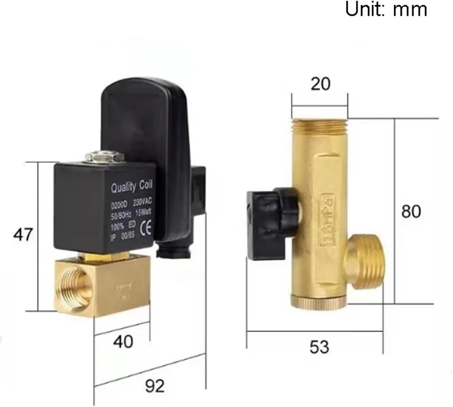
Figure 3: Approximate dimensions for the Type A drain valve and its associated manual ball valve. All measurements are in millimeters (mm).

Figure 4: Approximate dimensions for the 20W solenoid coil. The inner diameter is 13mm and the height is 41mm. This coil operates on AC230V.

Figure 5: Approximate dimensions for a 15W solenoid coil variant. The inner diameter is 14mm and the height is 41mm. This coil operates on AC230V. Note: This specific product is 20W, but this image shows a similar 15W coil for reference.
5. Installation
Before you begin: Ensure the air compressor system is completely depressurized and the power supply is disconnected.
- Select Location: Choose a suitable location at the lowest point of the air receiver tank or air dryer where condensate collects. The valve must be installed vertically with the solenoid coil facing upwards.
- Prepare Connection: Clean the threaded connection point on the tank. Apply thread sealant (e.g., PTFE tape) to the valve's inlet threads.
- Mount Valve: Carefully thread the drain valve into the connection point. Tighten securely but do not overtighten. Ensure the valve is oriented correctly (upright).
- Connect Drain Line: Attach a suitable drain hose or pipe to the outlet of the drain valve. Ensure the drain line is routed to an appropriate condensate disposal system, preventing environmental contamination.
- Electrical Connection: Connect the 220V AC power supply to the solenoid coil's electrical connector. Ensure proper grounding and secure all wiring connections. Refer to the wiring diagram on the timer module if available.
- Test System: Once installed, slowly repressurize the air system and check for any leaks. Reconnect the power supply to the drain valve.
6. Operating Instructions and Timer Settings
The electronic timer module allows you to set the interval between drain cycles and the duration of each drain cycle.
6.1 Timer Adjustment
The timer typically has two adjustment knobs or digital displays:
- 'ON' Time (Drain Duration): This setting determines how long the valve remains open to discharge condensate. Adjust this to a short duration (e.g., 0.5 to 5 seconds) sufficient to clear the condensate without excessive air loss.
- 'OFF' Time (Interval): This setting determines the time between drain cycles. Adjust this based on the amount of condensate generated by your system (e.g., 1 to 30 minutes). A higher condensate load requires a shorter interval.
Note: Start with conservative settings (longer interval, shorter drain duration) and adjust as needed based on observation of condensate accumulation and discharge efficiency.
6.2 Manual Drain (Type A Valve Only)
For Type A valves, the separate manual ball valve can be used to manually drain condensate or to isolate the electronic drain valve for maintenance. Turn the handle to open or close the manual valve as required.
7. Maintenance
Regular maintenance ensures the longevity and proper functioning of your drain valve.
- Daily Check: Observe the valve's operation to ensure it is draining condensate effectively and not continuously leaking.
- Weekly Inspection: Check for any signs of leaks around the valve body or connections. Inspect the drain line for blockages or damage.
- Monthly Cleaning: Disconnect power and depressurize the system. Remove the solenoid coil and valve body. Clean any debris or sludge from the valve's internal passages. Use a mild detergent if necessary, and rinse thoroughly. Reassemble carefully.
- Annual Service: Consider replacing seals or O-rings if signs of wear or leakage are present.
Important: Always disconnect power and depressurize the system before performing any maintenance.
8. Troubleshooting
| Problem | Possible Cause | Solution |
|---|---|---|
| Valve does not drain | No power; Timer set incorrectly; Valve clogged; Solenoid coil failure | Check power supply and connections; Adjust timer settings; Disconnect power, depressurize, and clean valve; Replace solenoid coil. |
| Valve drains continuously | Timer malfunction; Valve seat damaged/dirty; Debris preventing valve closure | Check timer settings; Disconnect power, depressurize, clean valve seat; Replace valve if damaged. |
| Air leakage from valve | Loose connections; Damaged seals/O-rings; Valve seat damage | Tighten connections; Replace seals/O-rings; Clean or replace valve. |
| Condensate not fully discharged | 'ON' time too short; Drain line blocked; Valve partially clogged | Increase 'ON' time; Clear drain line; Disconnect power, depressurize, and clean valve. |
9. Warranty and Support
For information regarding warranty coverage, technical support, or replacement parts, please contact your retailer or the manufacturer directly. Keep your purchase receipt as proof of purchase.
Manufacturer: CONTIA
