1. Introduction
This instruction manual provides detailed guidance for the proper installation, operation, and maintenance of the VCELINK Cat6 RJ45 1-Port Shielded Surface Mount Box. This product is designed to provide a convenient and reliable network termination point in locations where in-wall cabling is not practical or desired. Please read this manual thoroughly before installation and retain it for future reference.
2. Product Overview
The VCELINK Cat6 RJ45 1-Port Shielded Surface Mount Box offers a robust solution for extending network connectivity. It is compatible with Cat6, Cat5e, and Cat5 UTP solid or stranded network cables, supporting a maximum cable outside diameter of 6.2mm (0.24 inches). The box is Category 6 rated, ensuring performance up to Gigabit Ethernet speeds in compliance with ANSI/TIA/EIA 568-C.2 standards.
Key features include:
- Shielded Design: Features a 360° metal shielded housing to reduce EMI/RFI interference, promoting a more stable and faster connection.
- PoE Support: Supports Power over Ethernet (PoE) applications.
- Wiring Standards: Compatible with T568A and T568B wiring standards, utilizing 110-style, color-coded termination blocks.
- Tool Compatibility: Dual IDC terminals accept both 110 and Krone impact tools for termination.

Image: Exploded view of the surface mount box, highlighting the internal high-performance PCB board and 360° metal shielding for EMI/RFI interference reduction.
3. Package Contents
Each package contains the following items:
- VCELINK Cat6 RJ45 1-Port Surface Mount Box (quantity as per pack size)
- Mounting Screws (2 per box)
- Double-Sided Adhesive Tape (1 per box)

Image: Illustration of the package contents, including the surface mount box, snap-on cover, mounting screws, and double-sided tape. The internal wiring diagram is also indicated.
4. Setup and Installation
Follow these steps to install your VCELINK Cat6 RJ45 Surface Mount Box:
- Prepare the Cable: Carefully strip approximately 5-7 cm (2-2.7 inches) of the outer jacket from your network cable. Untwist the wire pairs, ensuring not to expose too much bare wire.
- Separate Wire Pairs: Carefully separate and straighten the individual wires.
- Open the Box: Gently pry open the surface mount box by separating the top cover from the base.
- Route the Cable: Feed the prepared network cable through the cable entry point at the back or side of the box.
- Secure the Cable: Use the integrated cable tie-down point (if available) or a small zip tie to secure the cable jacket inside the box, providing strain relief.
- Terminate Wires: Refer to the T568A or T568B wiring diagram located inside the box or below. Place each individual wire into its corresponding color-coded slot on the IDC termination block. Use a 110 or Krone impact tool to punch down each wire, ensuring a secure connection and trimming any excess wire.
- Close the Box: Once all wires are terminated and checked, snap the top cover back onto the base until it clicks securely into place.
- Mount the Box: Choose your preferred mounting method:
- Screws: Use the included mounting screws to attach the box to a wall, baseboard, or other surface.
- Adhesive Tape: Apply the included double-sided adhesive tape to the back of the box and press firmly onto a clean, dry surface.

Image: A network cable with its outer jacket removed, exposing the twisted wire pairs.

Image: The individual wires of the network cable are untwisted and straightened, ready for termination.

Image: The top cover of the surface mount box is being removed from its base.

Image: The prepared network cable is routed into the base of the surface mount box, positioned near the termination blocks.

Image: The network cable is secured within the box using a strain relief mechanism, preventing accidental dislodgement.

Image: A punch down tool is shown in action, terminating a wire into the IDC block. The image also highlights the phosphor bronze with tin-plated contacts.
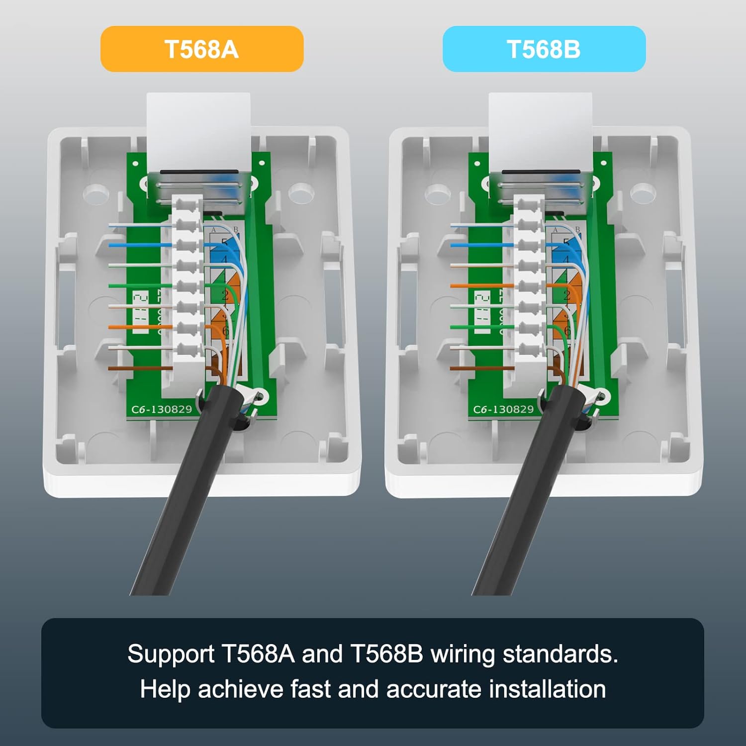
Image: Side-by-side comparison of T568A and T568B wiring standards, illustrating the correct color-coded placement of wires into the termination blocks for accurate installation.

Image: The dimensions of the surface mount box are provided, along with an illustration of a connected RJ45 cable, indicating support for PoE and a maximum cable diameter of 6.2mm.
5. Operating
Once the VCELINK Cat6 RJ45 Surface Mount Box is installed and terminated, it functions as a passive network port. To operate, simply connect a standard RJ45 Ethernet patch cable from your network device (e.g., computer, printer, access point) to the RJ45 port on the surface mount box. Ensure the connection is firm. The box will then facilitate network communication over the terminated cable.
6. Maintenance
The VCELINK Cat6 RJ45 Surface Mount Box requires minimal maintenance. Periodically, you may:
- Gently wipe the exterior of the box with a dry, soft cloth to remove dust.
- Ensure that connected Ethernet cables are securely seated and not under excessive strain.
- Inspect the mounting for stability, especially if using adhesive tape in high-traffic areas.
Avoid using harsh chemicals or abrasive materials for cleaning, as these may damage the product finish.
7. Troubleshooting
If you encounter issues with your network connection after installing the surface mount box, consider the following troubleshooting steps:
- No Network Connection:
- Verify that both ends of the Ethernet patch cable are securely connected to the network device and the surface mount box.
- Check the wiring inside the surface mount box. Ensure all wires are correctly punched down according to either the T568A or T568B standard and that no wires are loose or shorting.
- Test the network cable with a cable tester to confirm continuity and correct wiring.
- Ensure the network equipment (router, switch) is powered on and functioning correctly.
- Slow Network Speed:
- Confirm that all components in your network chain (cables, switches, network cards) are rated for Gigabit Ethernet speeds.
- Check for any kinks or damage to the network cable.
- Ensure the cable length does not exceed the maximum recommended length for Cat6 (100 meters or 328 feet).
- Verify that the shielding is properly maintained and not compromised, as this can lead to increased interference.
- Intermittent Connection:
- Re-punch any questionable wire terminations to ensure solid contact.
- Check for external sources of electromagnetic interference (EMI) near the cable run or the surface mount box.
8. Specifications
| Feature | Specification |
|---|---|
| Model Number | A169C |
| Product Dimensions | 2.58 x 1.93 x 0.98 inches |
| Weight | 6.35 ounces |
| Connector Type | RJ45 |
| Cable Type | Ethernet |
| Compatible Devices | CAT5, CAT5E, CAT6 |
| Max Cable Outer Diameter | 6.2mm (0.24 inches) |
| Performance Standard | Category 6 (ANSI/TIA/EIA 568-C.2) |
| Data Transfer Speed | Up to Gigabit Ethernet |
| Wiring Standards | T568A & T568B |
| Termination Type | 110-style IDC (accepts 110 or Krone impact tools) |
| Special Feature | 360° Metal Shielded Housing, PoE Support |
9. Warranty and Support
VCELINK provides an 18-month warranty for this product, covering manufacturing defects and ensuring reliable performance. For any questions, technical assistance, or warranty claims, please contact VCELINK customer service through the retailer where the product was purchased. Please have your purchase details and product model number (A169C) available when contacting support.


