1. Introduction
The HANMATEK HM5100 is a passive oscilloscope probe designed for general-purpose electronic measurements. It offers selectable 1X and 10X attenuation ratios and a bandwidth of up to 100 MHz, making it suitable for use with most digital, virtual, and portable oscilloscopes equipped with a standard BNC connector. This manual provides essential information for the safe and effective use of your HM5100 probe.
2. Product Overview
Familiarize yourself with the main components of the HM5100 oscilloscope probe.

Figure 2.1: Main components of the HM5100 probe, including the probe tip, probe rod, ground lead, and BNC connector.
- Probe Tip: The point of contact for signal measurement.
- Probe Rod: The main body of the probe, housing the attenuation switch.
- Ground Lead: Connects the probe to the circuit's ground reference.
- BNC Connector: Standard connector for attaching the probe to an oscilloscope input.
3. Specifications
| Parameter | Value |
|---|---|
| Model | HM5100 |
| Bandwidth | 100 MHz (10X), 6 MHz (1X) |
| Attenuation Ratio | 1X / 10X (Switchable) |
| Input Resistance | 1 MΩ (1X), 10 MΩ (10X) |
| Max Input Voltage | 200 Vpk (1X), 600 Vpk (10X) |
| Cable Length | Approximately 1.2 meters |
| Connector Type | Standard BNC |
| Package Dimensions | 17.91 x 11.51 x 2.21 cm |
| Weight | 82 g |
4. Setup
4.1 Connecting the Probe
- Connect the BNC connector of the HM5100 probe to an input channel on your oscilloscope.
- Attach the ground lead's alligator clip to the ground reference point of the circuit under test. Ensure a secure connection.
4.2 Setting Attenuation
The HM5100 probe features a switch on the probe rod to select between 1X and 10X attenuation. The selected attenuation must match the setting on your oscilloscope for accurate readings.

Figure 4.1: Attenuation ratio switch on the probe rod.
- 1X Mode: Provides a direct signal to the oscilloscope. Suitable for low-frequency signals where minimal loading is acceptable. The oscilloscope should be set to 1X probe attenuation.
- 10X Mode: Attenuates the signal by a factor of 10. This mode reduces circuit loading and increases the probe's bandwidth and input voltage range. The oscilloscope should be set to 10X probe attenuation. This is the most commonly used mode for general measurements.
4.3 Probe Compensation Adjustment
To ensure accurate signal reproduction, the probe's capacitance must be compensated to match the input capacitance of your oscilloscope. This adjustment should be performed when first using the probe with an oscilloscope or if you switch to a different oscilloscope.

Figure 4.2: Compensation adjustment screw location.
- Connect the probe to an oscilloscope channel and set the probe to 10X attenuation.
- Connect the probe tip to the oscilloscope's probe compensation output (usually a square wave signal) and the ground lead to the oscilloscope's ground terminal.
- Adjust the oscilloscope's time base and vertical sensitivity to display several cycles of the square wave.
- Using the provided non-metallic adjustment tool (see Figure 4.3), carefully turn the compensation screw on the BNC connector end of the probe until the square wave displayed on the oscilloscope has flat top and bottom edges, with no overshoot or undershoot.

Figure 4.3: Probe accessories, including the adjustment tool.
5. Operating Instructions
5.1 General Measurement
- Ensure the probe is correctly connected and compensated as described in Section 4.
- Select the appropriate attenuation (1X or 10X) on the probe and the oscilloscope. For most measurements, 10X is recommended.
- Carefully touch the probe tip to the test point on the circuit.
- Observe the waveform on the oscilloscope screen. Adjust the oscilloscope's vertical and horizontal controls as needed to obtain a stable and clear display.

Figure 5.1: Using the HM5100 probe with a desktop oscilloscope.

Figure 5.2: Using the HM5100 probe with a handheld oscilloscope.
5.2 Using Accessories
- Hook Protective Cap: Use this cap to securely attach the probe tip to test points, allowing for hands-free measurement.
- Ground Spring: For high-frequency measurements, replace the standard ground lead with the ground spring for a shorter ground path, reducing inductance and improving signal integrity.
- Positioning Sleeves: These sleeves are useful for testing integrated circuits (ICs) or other small components, providing stability and preventing accidental short circuits.

Figure 5.3: Using a positioning sleeve for IC testing.
- Marking Rings: If using multiple probes, attach the colored marking rings to differentiate between them, especially useful for multi-channel measurements.
5.3 Safety Precautions
- Always ensure the probe's maximum input voltage rating is not exceeded.
- Connect the ground lead before connecting the probe tip to the signal. Disconnect the probe tip before disconnecting the ground lead.
- Avoid touching exposed metal parts of the probe or circuit while power is applied.
- Use the hook protective cap or positioning sleeves when possible to prevent accidental contact.
6. Maintenance
- Keep the probe clean and dry. Use a soft, damp cloth to wipe the probe body. Do not use abrasive cleaners or solvents.
- Store the probe and its accessories in a protective case or a clean, dry environment when not in use to prevent damage.
- Regularly inspect the cable and connectors for any signs of wear or damage. Do not use a damaged probe.
7. Troubleshooting
- No Signal or Weak Signal:
- Check if the probe is securely connected to the oscilloscope and the circuit.
- Ensure the ground lead is properly connected.
- Verify that the attenuation setting on the probe matches the oscilloscope's setting. - Distorted Waveform (e.g., rounded or spiked square wave):
- Perform probe compensation adjustment as described in Section 4.3. - Excessive Noise:
- Ensure the ground connection is solid and as short as possible.
- Use the 10X attenuation mode to reduce circuit loading and improve signal-to-noise ratio.
8. Package Contents
The HANMATEK HM5100 Passive Oscilloscope Probe package includes the following items:
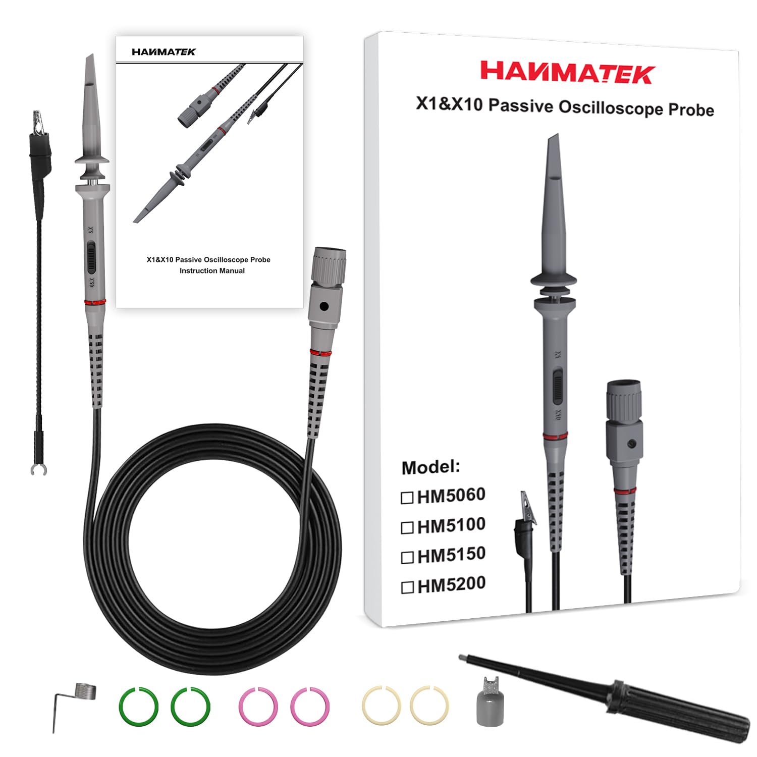
Figure 8.1: Contents of the HM5100 package.
- 1 x HANMATEK HM5100 Oscilloscope Probe (100 MHz)
- 1 x Hook Protective Cap
- 1 x Ground Clip (alligator clip)
- 6 x Marking Rings (various colors)
- 1 x Ground Spring
- 1 x Positioning Sleeve
- 1 x Adjustment Rod (non-metallic)
- 1 x User Manual
9. Warranty and Support
HANMATEK products are designed for reliability and performance. For warranty information or technical support, please refer to the contact details provided with your purchase documentation or visit the official HANMATEK website. Please retain your proof of purchase for warranty claims.


