1. Introduction
This manual provides essential information for the safe and efficient operation of your LiTime 60 Amp MPPT Solar Charge Controller. Please read this manual thoroughly before installation and use. This controller is designed to optimize power harvesting from solar panels to charge various battery types, including LiFePO4 and Lead-acid batteries, across 12V, 24V, and 48V systems.
Key features include:
- Advanced Maximum Power Point Tracking (MPPT) technology with 99% tracking efficiency and up to 96% peak conversion efficiency.
- Compatibility with multiple system voltages (12V/24V/48V for LiFePO4 and 12V/24V/36V/48V/Auto for Lead-acid batteries).
- Integrated LCD screen and LED indicators for system monitoring.
- Robust sheet metal shell with dual forced cooling for effective heat dissipation.
- Comprehensive safety protections against overpower, over-voltage, short-circuit, and over-temperature.
2. What's in the Box
Upon unpacking, please verify that all items listed below are present and undamaged. If any components are missing or damaged, contact customer support immediately.

Image: The contents of the product box, including the controller, manual, and accessories.
- LiTime 60 Amp MPPT Solar Charge Controller
- Product Manual
- Magic Sticker (1)
- Remote Temperature Sensor (1)
- Screws (4)
- Plastic Anchors (4)
- Copper Wire Connectors (6)
- Heat Shrink Tubes (3 pairs)
3. Product Overview
3.1 Component Identification

Image: A detailed view of the controller's connection ports and mounting points.
- Grounding Terminal: For connecting the system ground.
- Remote Temperature Sensor Port: Connects the external temperature sensor for accurate battery temperature compensation.
- Solar Panel Terminals (PV+ / PV-): Connects to the solar panel array.
- Battery Terminals (BAT+ / BAT-): Connects to the battery bank.
- DC Load Terminals (LOAD+ / LOAD-): Connects to DC loads.
- Communication Port (RS485): For external communication devices.
- Mounting Holes: Used to secure the controller to a surface.
3.2 Display and Operation Keys
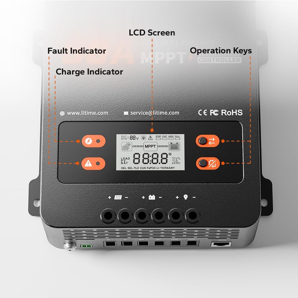
Image: A close-up of the controller's LCD screen, charge indicator, fault indicator, and operation keys.
- LCD Screen: Displays real-time system operation information.
- Charge Indicator: Illuminates to show charging status.
- Fault Indicator: Illuminates to indicate system errors or faults.
- Operation Keys: Two buttons (S Key and OK Key) for navigating menus and setting parameters.
4. Setup and Installation
4.1 Choosing a Mounting Location
Select a dry, well-ventilated area away from direct sunlight, high temperatures, and moisture. Ensure adequate clearance around the controller for proper heat dissipation.

Image: A diagram showing the required ventilation clearances for mounting the controller, with at least 12 inches (30cm) above and below, and 2 inches (5cm) on both sides.
- Maintain at least 12 inches (30cm) of clearance above and below the controller.
- Maintain at least 2 inches (5cm) of clearance on both sides.
4.2 Mounting the Controller
The controller can be mounted on a wood wall or drywall using the provided screws and plastic anchors.
- On Wood Wall: Align the controller and fix it directly with screws.
- On Drywall: Drill holes, insert plastic anchors, then align and fix the controller with screws.
4.3 Wiring Connections
WARNING: Ensure all power sources are disconnected before making any connections. Incorrect wiring can damage the controller, batteries, or solar panels.
Follow the connection sequence below to prevent damage:
- Connect the battery bank to the Battery Terminals (BAT+ / BAT-).
- Connect the DC loads to the DC Load Terminals (LOAD+ / LOAD-).
- Connect the solar panel array to the Solar Panel Terminals (PV+ / PV-).
- Connect the Remote Temperature Sensor to its dedicated port.
- Connect the Grounding Terminal to the system ground.

Image: An illustration of a complete solar power system setup, showing the connections between solar panels, the charge controller, battery, and an inverter/load.
4.4 Recommended Cable Size and Fuse
Proper cable sizing and fusing are critical for safety and performance.

Image: A table detailing recommended wire gauge and fuse sizes for solar panel/battery and load connections.
| Connection | Wire Gauge Recommendation | Fuse Recommendation (1.2 to 1.5 times max continuous current) |
|---|---|---|
| Solar Panel/Battery | 6 AWG | 72A to 90A |
| Load | 10 AWG | 36A to 45A |
5. Operating Instructions
5.1 LCD Display and Indicators
The LCD screen provides real-time data, while LED indicators offer quick status updates.
- LCD Screen: Displays battery voltage, charging current, load current, system status, and error codes.
- Charge Indicator: Solid green when charging, flashing green during float charge, off when not charging.
- Fault Indicator: Solid red indicates a fault; refer to the troubleshooting section for details.
5.2 Operation Keys (S Key & OK Key)
The two buttons allow you to view system data and configure settings.

Image: A table detailing the functions of the 'S Key' and 'OK Key' for navigating and setting parameters on the controller's display.
| Key | Operation | Function |
|---|---|---|
| S Key | Short Press | View Real-time Data |
| S Key | Press and Hold | Not applicable |
| OK Key | Short Press | View Set Parameters |
| OK Key | Press and Hold | Enter Set Mode |
| Key | Operation | Function |
|---|---|---|
| S Key | Short Press | View Previous Page |
| S Key | Press and Hold | Exit Set Mode without Saving |
| OK Key | Short Press | View Next Page |
| OK Key | Press and Hold | Save Data & Exit Set Mode |
5.3 Battery Type and System Voltage Configuration
The controller supports LiFePO4 and Lead-acid batteries. Parameters can be adjusted via the LCD screen in Set Mode.
- LiFePO4 Battery Charging Mode: Supports 12V, 24V, and 48V systems.
- Lead-acid Battery Charging Mode: Supports 12V, 24V, 36V, 48V, and Auto-detection systems.

Image: A table outlining the compatibility of the controller with LiFePO4 and Lead Acid batteries across different system voltages, along with maximum solar input power, PV input voltage, rated charging current, and rated load current.
6. Maintenance
Regular maintenance ensures optimal performance and longevity of your solar charge controller.
- Cleanliness: Keep the controller clean and free from dust and debris. Use a dry cloth for cleaning.
- Connections: Periodically check all wiring connections to ensure they are tight and free from corrosion.
- Ventilation: Ensure the ventilation openings are not blocked to allow for proper airflow. The dual forced cooling system relies on clear airflow for effective heat dissipation.
- Temperature Sensor: Ensure the remote temperature sensor is securely attached to the battery for accurate temperature readings.
7. Troubleshooting
The controller is equipped with multiple protection features to ensure safe operation. If the Fault Indicator illuminates, refer to the list below for potential issues.

Image: An illustration highlighting the nine safety protection features integrated into the solar charge controller.
7.1 Safety Protections
The LiTime MPPT controller includes the following safety protections:
- PV Over-voltage Protection
- PV Reverse Polarity Protection
- PV Short-circuit Protection
- Battery Over-voltage Protection
- Battery Under-voltage Protection
- Battery Reverse Connection Protection
- Load Over Current Protection
- Controller Over-temp Protection
- Low-temp Charging Protection (LTCP) for lithium batteries (stops charging below 0°C/32°F, resumes at ≥5°C/41°F).

Image: A visual explanation of the Low-Temperature Charging Protection (LTCP) feature, showing the temperature thresholds for stopping and resuming charging.
7.2 Common Issues and Solutions
- No Power/Display: Check battery connections and ensure the battery voltage is within the controller's operating range.
- No Charging: Verify solar panel connections, ensure sufficient sunlight, and check for PV over-voltage or short-circuit faults.
- Load Not Working: Check load connections, ensure the load current does not exceed the rated capacity, and verify battery voltage is above the low voltage disconnect setting.
- Over-temperature Fault: Ensure adequate ventilation around the controller. Reduce load or solar input if operating in extreme ambient temperatures.
For persistent issues, please contact LiTime customer support.
8. Specifications
Detailed technical specifications for the LiTime 60 Amp MPPT Solar Charge Controller.
| Parameter | Value |
|---|---|
| Brand | Litime |
| Model Number | L48V-60A-MPPT-BT-US-2 |
| Rated Charging Current | 60A |
| Rated Load Current | 30A |
| System Voltage | 12V/24V/48V (LiFePO4), 12V/24V/36V/48V/Auto (Lead Acid) |
| Max. PV Input Voltage | 150V |
| Max. Solar Panel System Input Power (12V) | 870W |
| Max. Solar Panel System Input Power (24V) | 1740W |
| Max. Solar Panel System Input Power (36V) | 2610W |
| Max. Solar Panel System Input Power (48V) | 3480W |
| Tracking Efficiency | ≥99% |
| Peak Conversion Efficiency | Up to 96% |
| Display Type | LCD |
| Operating Temperature | Up to 50°C |
| Product Dimensions (L x W x H) | 6.57 x 2.76 x 8.66 inches (167 x 70 x 220 mm) |
| Item Weight | 3.75 pounds (1.7 kg) |
| Material | Steel |
| Color | Black |
9. Warranty and Support
LiTime provides professional technical support and customer service. If you have any questions or require assistance, please do not hesitate to contact us.
- Technical Support: Available via phone or online services.
- Response Time: Quick feedback within 24 hours.
- Contact Email: service@litime.com
For warranty details, please refer to the warranty card included with your product or visit the official LiTime website.


