1. Introduction
This manual provides comprehensive instructions for the installation, operation, maintenance, and troubleshooting of the Datakom D-300-MK3 Multifunctional Generator Controller. The D-300-MK3 is designed for advanced genset control and monitoring, offering a wide range of features for various applications.
Please read this manual thoroughly before attempting to install or operate the device to ensure safe and efficient use.
2. Product Overview
The Datakom D-300-MK3 is a versatile generator controller featuring modern technology for reliable genset management. Key functionalities include:
- AMF (Automatic Mains Failure) unit capabilities
- ATS (Automatic Transfer Switch) unit capabilities
- Remote start control
- Manual start control
- Engine control functions
- Harmonic analysis and detailed power measurements
- Easy firmware upgrade via USB port
- Monitoring and programming via USB, RS-232, and GPRS using Windows-based PC software
- Web-based monitoring and control through Rainbow Scada service
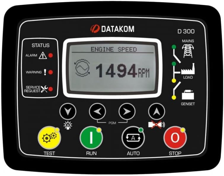
Figure 2.1: Datakom D-300-MK3 Front Panel. This image displays the front interface of the D-300-MK3 controller, showing the LCD screen, status indicators (Alarm, Warning, Service Request), and control buttons (TEST, RUN, AUTO, STOP, navigation buttons, PGM button).
3. Installation and Setup
Proper installation is crucial for the safe and reliable operation of the D-300-MK3 controller. Ensure all connections are secure and follow local electrical codes.
3.1. Physical Installation
Mount the controller in a suitable enclosure, protected from environmental elements. Ensure adequate ventilation to prevent overheating.
3.2. Wiring Connections
Refer to the wiring diagrams for detailed connection instructions. All wiring should be performed by qualified personnel.

Figure 3.1: Typical Connections Diagram. This diagram illustrates the standard wiring for the D-300-MK3, showing connections for the alternator, mains, load, battery, starter, fuel pump, oil pressure, high temperature, and various sensors and inputs. It also highlights the USB port and communication extension.
Key Connection Points:
- Power Supply: Connect the controller to a stable DC power source (e.g., battery). Ensure correct polarity.
- Generator Connections: Connect the generator's voltage and current inputs to the designated terminals.
- Mains Connections: For AMF applications, connect the mains voltage inputs.
- Engine Control: Connect the starter, fuel solenoid, and other engine control outputs.
- Sensors: Connect engine sensors such as oil pressure, coolant temperature, and fuel level.
- J1939: For engines supporting J1939 CAN bus communication, connect the J1939 lines.
- Grounding: Ensure proper grounding of the controller and associated equipment. Battery negative must be grounded. Connect to the engine body, close to the senders.

Figure 3.2: Datakom D-300-MK3 Back Panel. This image shows the rear view of the controller, detailing the various terminal blocks for input/output connections, the USB port, and the slot for plug-in communication modules. It indicates power requirements (8 to 36Vdc, 500mA max) and AC input specifications (300Vac, 0-600 Hz, 0.2 to 6.0 Aac).

Figure 3.3: Back Panel View and Plug-in Modules. This image provides a clearer view of the D-300-MK3's back panel, emphasizing the "PLUG-IN COMM. MODULE" slot. It also displays various optional plug-in communication modules: GSM Modem (with SIM and Antenna), RS-485, Ethernet, RS-232, and Wi-Fi, illustrating the controller's expandability.
3.3. Initial Configuration
After wiring, power on the unit. The controller will perform a self-test. Use the navigation buttons and the PGM button to access the setup menus. Configure parameters such as:
- System type (e.g., single phase, three phase)
- Generator and mains voltage/current ratings
- Engine start/stop parameters
- Alarm thresholds and actions
- Communication settings (if using optional modules)
Detailed parameter settings are available in the advanced programming guide (refer to Datakom website).
4. Operation
The D-300-MK3 offers multiple operating modes, controlled via the front panel buttons.
4.1. Control Buttons
- TEST (Yellow Gear Icon): Initiates a generator test run.
- RUN (Green 'I' Icon): Starts the generator manually.
- AUTO (Blue 'A' Icon): Activates Automatic Mains Failure (AMF) mode, allowing the controller to automatically start/stop the generator based on mains power status.
- STOP (Red 'O' Icon): Stops the generator manually.
- Navigation Buttons (Arrows): Used to navigate through menus and adjust parameters on the LCD display.
- PGM Button: Used to enter programming mode or confirm selections.
4.2. Display Information
The LCD display provides real-time information about the generator, mains, and controller status. This includes engine speed, voltage, current, frequency, power, and various alarms or warnings.
4.3. Communication and Monitoring
The D-300-MK3 supports various communication methods for remote monitoring and control.

Figure 4.1: Communication Diagram. This diagram illustrates the extensive communication capabilities of the D-300-MK3. It shows connections for GSM-SMS, E-mail, Central Monitoring (Rainbow Scada), Remote Display Panel, HMI Display, PLC, and PC via USB, RS-485, Ethernet, Wi-Fi, and GSM. It also highlights the J1939 connection to the electronic engine for data exchange.
- USB Port: For local connection to a PC for configuration and monitoring using Datakom's Windows-based software. Also used for firmware upgrades.
- RS-232/RS-485: Serial communication ports for local or remote connection to PCs or other control systems.
- GPRS/GSM Modem (Optional): Enables SMS messaging, email alerts, and remote monitoring via cellular networks.
- Ethernet/Wi-Fi (Optional): Provides network connectivity for local area network (LAN) or internet-based monitoring.
- Rainbow Scada Web Service: Allows monitoring and control of multiple gensets from a central web-based platform.
- J1939: For communication with electronic engines, providing access to engine parameters and diagnostic information.
5. Maintenance
Regular maintenance ensures the longevity and reliable operation of your D-300-MK3 controller.
- Cleaning: Keep the controller's front panel clean and free of dust. Use a soft, dry cloth. Do not use abrasive cleaners or solvents.
- Connections: Periodically check all wiring connections for tightness and signs of corrosion. Loose connections can lead to intermittent operation or damage.
- Firmware Updates: Check the Datakom website for available firmware updates. Updating the firmware can provide new features and improve performance.
- Environmental Conditions: Ensure the operating environment remains within the specified temperature and humidity ranges.
6. Troubleshooting
This section provides basic troubleshooting steps for common issues. For more complex problems, consult the advanced technical manual or contact Datakom support.
| Problem | Possible Cause | Solution |
|---|---|---|
| Controller does not power on. | No power supply; incorrect wiring; blown fuse. | Check battery connections and voltage. Verify wiring. Inspect and replace fuses if necessary. |
| Generator fails to start. | Low fuel; low battery; engine fault; incorrect start parameters. | Check fuel level and battery charge. Inspect engine for faults. Verify start parameters in controller settings. |
| Communication issues (e.g., no remote monitoring). | Incorrect communication settings; network issues; module not installed correctly. | Verify communication module installation. Check network connectivity. Review communication parameters in controller settings. |
| Alarm/Warning indicator active. | Engine fault; sensor error; operational limit exceeded. | Check the display for the specific alarm message. Address the underlying issue (e.g., low oil pressure, high temperature). Consult the alarm code list in the advanced manual. |
7. Specifications
The following specifications apply to the Datakom D-300-MK3 Multifunctional Generator Controller:
- Brand: DATAKOM
- Model: D-300-MK3
- Included Components: Multifunctional Generator Controller
- Material: Copper (likely referring to internal components/contacts)
- Item Weight: 1.12 pounds (0.51 Kilograms)
- Manufacturer: DATAKOM
- Input Voltage: 8 to 36 VDC (Controller Power Supply)
- AC Input: 300 Vac, 0-600 Hz, 0.2 to 6.0 Aac (for generator/mains sensing)
- Communication Interfaces: USB, RS-232, RS-485, GPRS, Ethernet, Wi-Fi, J1939 (some via optional plug-in modules)
8. Warranty and Support
For warranty information, please refer to the documentation provided with your purchase or contact your Datakom distributor. Datakom products typically come with a manufacturer's warranty covering defects in materials and workmanship.
For technical support, advanced troubleshooting, or spare parts, please contact Datakom customer service or visit the official Datakom website for support resources and contact details.


