1. Introduction
The Datakom D-300-MK2 is a cost-effective, modular genset controller designed for internet monitoring through plug-in modules. It functions as an AMF (Automatic Mains Failure) unit, ATS (Automatic Transfer Switch) unit, remote start controller, manual start controller, and engine controller. This manual provides essential information for the proper installation, operation, and maintenance of the D-300-MK2 controller.

Figure 1.1: Front view of the D-300-MK2 controller, highlighting its features and functionalities.
2. Key Features and Functionalities
The D-300-MK2 controller offers a wide range of features and functionalities for comprehensive genset management:
2.1. General Features
- Diesel and gas genset support
- 400Hz operation support
- 400 event logs, full snapshot
- All parameters front panel editable
- 3-level configuration password
- 128x64 graphical LCD display
- Downloadable languages
- Waveform display of V & I
- Harmonic analysis of V & I
- 16Amp MCB & GCB outputs
- 8 configurable digital inputs
- 6 configurable digital outputs
- 2 configurable analog inputs
- Both CANBUS-J1939 & MPU
- 3 configurable service alarms
- Multiple automatic exercise
- Weekly operation schedule
- Dual mutual standby with equal aging of gensets
- Manual "speed fine adjust" on selected ECUs
- Automatic fuel pump control
- Disable protections feature
- Excess power protection
- Reverse power protection
- Overload IDMT protection
- Load shedding, dummy load
- Multiple load management
- Current unbalance protection
- Voltage unbalance protection
- Fuel filling & fuel theft alarm
2.2. Advanced Features
- Battery back-up real time clock
- Idle speed control
- Battery charge run enabled
- Contactor mode support
- Multiple nominal conditions
- Contactor & MCB drive
- 4 quadrant genset power counters
- Mains power counters
- Fuel filling counter
- Fuel consumption counter
- Modem diagnostics display
- Configurable through USB, RS-232 and GPRS
- Free configuration program
- Allows SMS controls
- Ready for central monitoring
- Mobile genset support
- Automatic GSM geo-location
- GPS connectivity (RS232)
- Easy USB firmware upgrade
- Free rating with external gasket
2.3. Functionalities
- AMF unit
- ATS unit
- Manual start controller
- Engine controller
- Remote display panel
3. Product Overview and Plug-in Modules
The D-300-MK2 controller features a robust design with various connection points and supports modular extensions for enhanced communication capabilities.
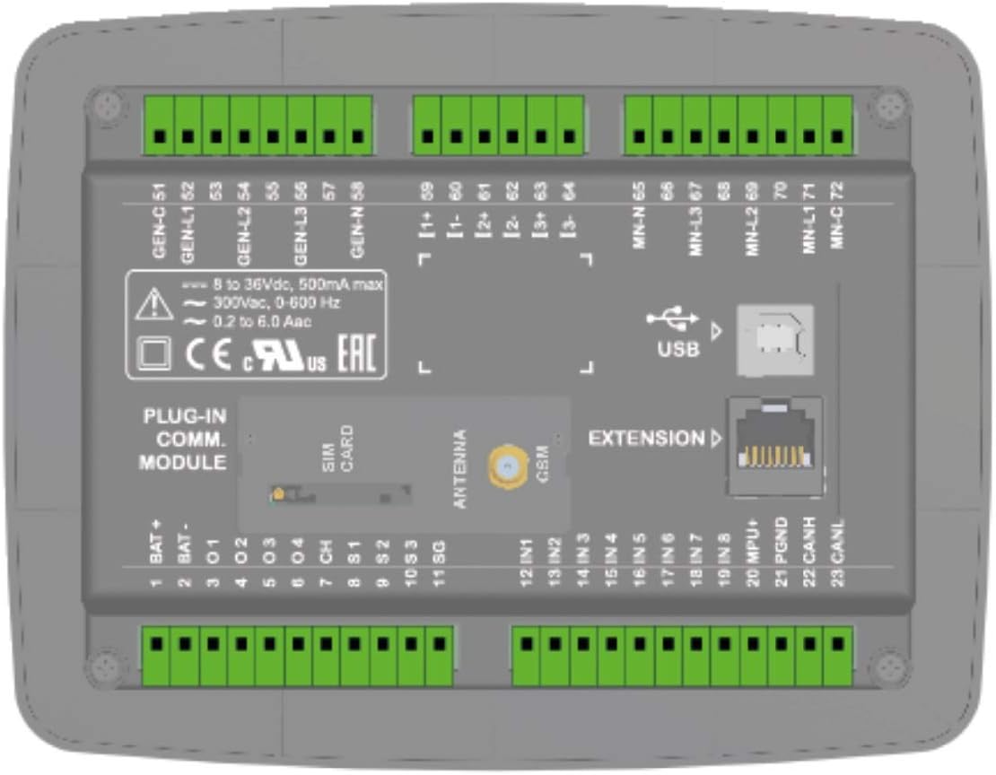
Figure 3.1: Detailed back panel view of the D-300-MK2 controller, showing all terminal connections and module slots.
3.1. Plug-in Communication Modules
The D-300-MK2 supports various plug-in modules to extend its communication capabilities, allowing for internet monitoring and remote control.
- GSM Modem (2G-3G-4G): For cellular communication and SMS controls.
- Ethernet (10/100Mbps): For wired network connectivity.
- Wi-Fi (802.11 b/n): For wireless network connectivity.
- RS-485 (2400-57600baud): For industrial communication protocols.
- RS-232 (2400-57600baud): For serial communication, including GPS connectivity.
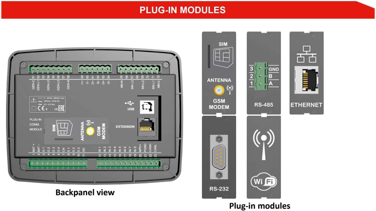
Figure 3.2: Illustration of various plug-in modules available for the D-300-MK2 controller, including GSM Modem, RS-485, Ethernet, RS-232, and Wi-Fi.
4. Technical Specifications
Understanding the technical specifications is crucial for proper installation and operation.
- Alternator voltage: 0 to 300 V-AC (Ph-N)
- Alternator frequency: 0-650 Hz.
- Mains voltage: 0 to 300 V-AC (Ph-N)
- Mains frequency: 0-650 Hz.
- Topology: 1-2-3 phase, with or without neutral
- DC Supply Range: 8.0 to 36.0 V-DC.
- VA-cos accuracy: 0.5% + 1 digit
- kVA-kW-kVAr accuracy: 1.0% + 1 digit
- Current consumption: 80 mA DC max @ 12V-DC
- Current inputs: current transformers, ../5A or ../1A.
- Digital inputs: input voltage 0 to 36 V-DC.
- Analog input range: 0-5000 ohms
- Mains and genset contactor outputs: 16Amps@250V
- DC Outputs: Protected mosfet semiconductor outputs, rated 1Amp@28V DC.
- Cranking dropouts: survives 0V for 100ms.
- Magnetic pickup voltage: 0.5 to 50V-AC.
- Magnetic pickup frequency: 0 to 10000 Hz.
- Charge Alternator Excitation: 2W.
- Display screen: 2.9", 128x64 pixels
- USB Device: USB 2.0 Full speed
- Operating temperature: -20°C to 70°C (-4 to +158°F)
- Storage temperature: -40°C to 80°C (-40 to +176°F)
- Maximum humidity: 95% non-condensing.
- IP Protection: IP65 from front panel, IP30 from the rear (with gasket)
- Dimensions: 180 x 140 x 46mm (WxHxD)
- Panel Cut-out Dimensions: 151 x 111 mm minimum.
- Weight: 300 g (approx.)
- Case Material: High temperature, non-flammable ABS/PC
- Installation: Flat surface mounting on a Type 1 enclosure. Rear retaining plastic brackets.
5. Installation and Wiring
Correct installation and wiring are critical for the safe and reliable operation of the D-300-MK2 controller. Refer to the wiring diagram for detailed connections.
5.1. Typical Connections
The diagram below illustrates the typical wiring for the D-300-MK2, including connections for the alternator, mains, and engine control.

Figure 5.1: Typical wiring diagram for the D-300-MK2 controller, showing connections to alternator, mains, and engine components. Ensure all connections are made according to local electrical codes and safety standards.
- Battery Connections: Connect BAT+ and BAT- terminals to the battery. Ensure battery negative is grounded.
- Alternator Connections: Connect alternator phases (L1, L2, L3, N) to the designated terminals.
- Mains Connections: Connect mains phases (L1, L2, L3, N) to the designated terminals.
- Engine Control: Connect starter motor, fuel solenoid, and other engine sensors (oil pressure, water temp, etc.) as per the diagram.
- MPU/J1939: Connect MPU (Magnetic Pickup Unit) or J1939 CANBUS for engine speed and data.
- Fuses: Install appropriate fuses for all power lines as indicated in the diagram.
- Grounding: Ensure proper grounding for all components.
6. Operation
The D-300-MK2 offers various operating modes to suit different genset applications.
6.1. Control Modes
- Manual Start: Allows the user to manually start and stop the genset using the front panel buttons.
- Remote Start: Enables starting and stopping the genset via a remote signal.
- Automatic Mains Failure (AMF): The controller automatically starts the genset upon detecting a mains power failure and transfers the load. It stops the genset and transfers the load back to mains when mains power is restored.
- Automatic Transfer Switch (ATS): Manages the transfer of load between mains and genset power sources.
6.2. Monitoring and Communication
The D-300-MK2 provides extensive monitoring capabilities and supports various communication methods for remote access and data logging.

Figure 6.1: Communication diagram illustrating how the D-300-MK2 connects to various systems for monitoring and control, including GSM, Wi-Fi, Ethernet, RS-485, J1939, and USB.
- Local Monitoring: The 128x64 graphical LCD display provides real-time data, alarms, and event logs.
- USB Connectivity: For local configuration and firmware updates using a PC.
- Remote Monitoring: Through plug-in modules (GSM, Ethernet, Wi-Fi, RS-485, RS-232), the controller can communicate with central monitoring systems, HMI displays, and smartphones.
- J1939/MPU: Supports communication with electronic engines for engine data.

Figure 6.2: Back panel view alongside screenshots of the Scopemeter & Harmonics display, Rainbow Plus Program, Rainbow SCADA Central Monitoring, and Smartphone Support, demonstrating the comprehensive monitoring capabilities.
6.3. Software Support
- Rainbow Plus Program: A free PC software for configuration, monitoring, and diagnostics.
- Rainbow SCADA Central Monitoring: For advanced remote monitoring and control of multiple gensets.
- Smartphone Support: Allows monitoring and control via a dedicated smartphone application.
7. Maintenance
Regular maintenance ensures the longevity and reliable operation of your D-300-MK2 controller and the genset it manages.
- Cleaning: Keep the controller's front panel clean and free from dust. Use a soft, dry cloth. Avoid abrasive cleaners or solvents.
- Connections Check: Periodically inspect all wiring connections for tightness and corrosion. Loose connections can lead to intermittent operation or damage.
- Firmware Updates: Check the manufacturer's website for available firmware updates to ensure optimal performance and access to new features. Updates can typically be performed via the USB port.
- Battery Check: Ensure the genset's battery, which powers the controller, is in good condition and properly charged.
- Environmental Conditions: Ensure the operating environment remains within the specified temperature and humidity ranges to prevent damage.
8. Troubleshooting
This section provides general guidance for common issues. For complex problems, consult a qualified technician or Datakom support.
- Controller Not Powering On:
- Check battery connections and voltage.
- Verify fuses are intact.
- Genset Not Starting:
- Check fuel level and battery charge.
- Inspect engine fault codes on the controller display.
- Verify all safety shutdowns are clear.
- Communication Issues:
- Ensure plug-in modules are correctly installed.
- Check network cables (Ethernet) or Wi-Fi signal strength.
- Verify SIM card (GSM) is active and has credit.
- Confirm correct IP addresses and port settings in software.
- Incorrect Readings:
- Check sensor connections and calibration.
- Verify CT (Current Transformer) ratios are correctly configured.
9. Conformity
The D-300-MK2 controller complies with relevant international standards and directives.
- EU Directives Conformity:
- 2014/35/EC (low voltage)
- 2014/30/EC (electro-magnetic compatibility)
- Norms of reference:
- EN 61010 (safety requirements)
- EN 61326 (EMC requirements)
- UL & CSA Compatibility:
- -UL 6200, Controls for Stationary Engine Driven Assemblies (Certificate #: 20140725-E314374)
- -CAN/CSA C22.2 No. 14-13 - Industrial Control Equipment
10. Support and Contact Information
For further assistance, technical support, or inquiries, please contact Datakom Electronics Limited:
- Tel: +90-216 466 84 60
- Fax: +90-216 364 65 65
- E-mail: datakom@datakom.com.tr
- Website: http://www.datakom.com.tr