D-500-MK3 Multifunctional Generator Controller
Model: D-500-MK3 | Brand: Datakom
User Manual
1. Introduction and Overview
The Datakom D-500-MK3 is a state-of-the-art genset controller designed for comprehensive management of generator sets. It integrates multi-functionality with extensive communication capabilities, offering a reliable and cost-effective solution for various power generation applications. This single controller supports synchronization, load sharing, Automatic Mains Failure (AMF), Automatic Transfer Switch (ATS), remote start, engine control, and remote display panel functionalities.
The D-500-MK3 is equipped for remote monitoring via GSM or Ethernet through optional plug-in communication modules. Its modular design allows for unlimited expansion, enabling the system to meet diverse operational requirements. The unit adheres to and often surpasses stringent industrial safety, vibration, and environmental standards. Firmware upgrades are simplified through a USB port, and the Windows-based PC software facilitates monitoring and programming via USB, RS-485, Ethernet, and GPRS. The Rainbow Scada web monitoring service provides web-based control and monitoring for an unlimited number of gensets.
2. Key Features
- Multi genset synchronizer and load share capabilities.
- Multi genset mains synchronizer functionality.
- Single genset parallel operation with mains.
- AMF (Automatic Mains Failure) unit with uninterrupted transfer.
- ATS (Automatic Transfer Switch) unit with uninterrupted transfer.
- Remote start controller functionality.
- Manual start controller functionality.
- Integrated MPU (Magnetic Pickup Unit) and J1939 CAN bus support.
- Expandable with various plug-in communication modules (GSM, Ethernet, etc.).
- USB port for easy firmware upgrades and PC connection.
- Windows-based PC software for comprehensive monitoring and programming.
- Compatibility with Rainbow Scada web monitoring service.
3. What's in the Box
Upon unpacking your D-500-MK3, please ensure all components are present and undamaged:
- D-500-MK3 Genset Controller (with MPU + J1939 support)
Note: Additional plug-in modules or accessories may be sold separately.
4. Setup and Installation
Proper installation is crucial for the reliable operation of the D-500-MK3 controller. This section provides an overview of physical mounting and electrical connections.
4.1 Physical Mounting
The D-500-MK3 is designed for panel mounting. Ensure adequate space for ventilation and access to the rear connections. Use appropriate fasteners to secure the unit firmly in place.
4.2 Electrical Connections
All electrical connections are made to the terminals on the rear of the controller. Refer to the wiring diagram below for detailed connection points for alternator, mains, load, battery, and various sensors and inputs/outputs.
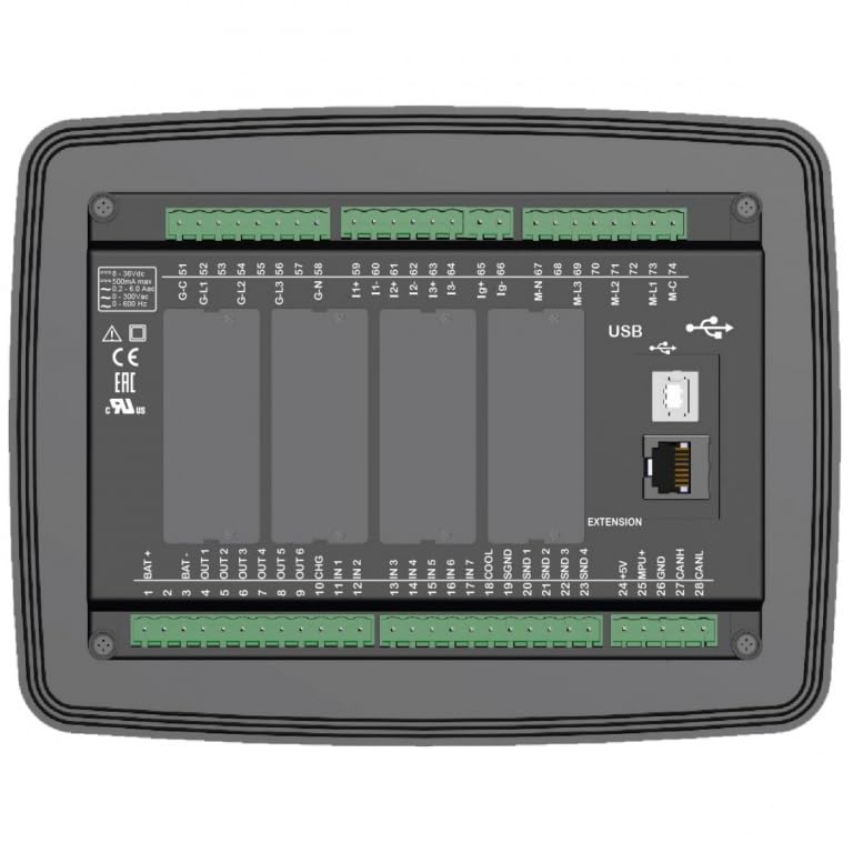
Figure 4.2.1: Rear view of the D-500-MK3 controller, illustrating the layout of all connection terminals, USB port, Ethernet port, and slots for plug-in modules. This view is essential for understanding the physical interface for wiring.
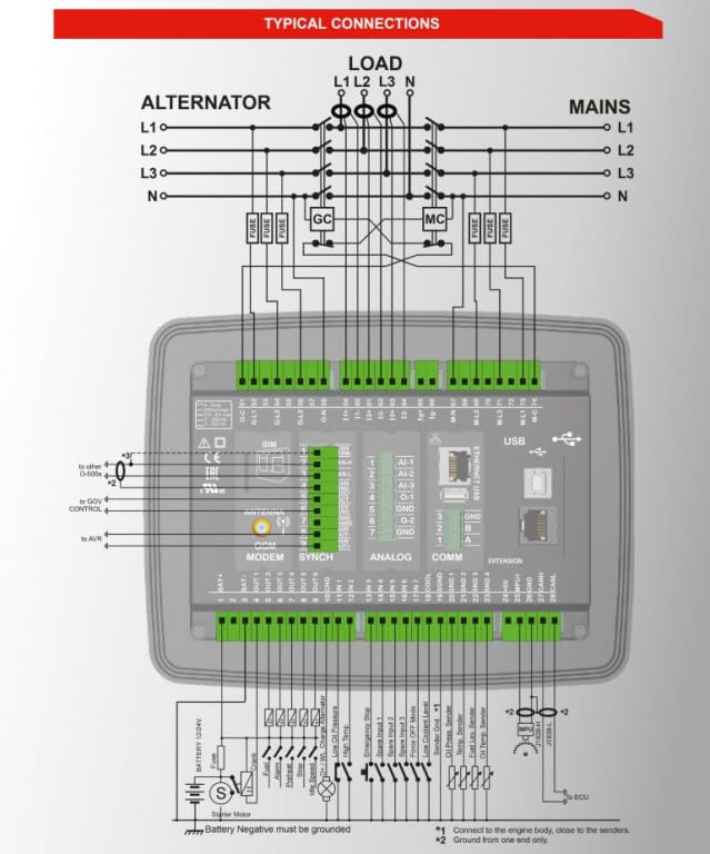
Figure 4.2.2: Detailed typical connection diagram for the D-500-MK3. This diagram shows the wiring for alternator, mains, load, battery, various inputs (e.g., oil pressure, water temperature), outputs, and communication lines (CAN bus, USB, Ethernet). Ensure all connections are made according to this schematic for proper operation.
Important: Ensure the battery negative is properly grounded. Refer to the diagram for specific grounding points and connections to the engine body.
4.3 Plug-in Modules
The D-500-MK3 supports various plug-in modules to extend its functionality, including GSM modem, synchronization modules, analog input modules, and communication modules (Ethernet, USB). These modules are inserted into designated slots on the rear of the unit.
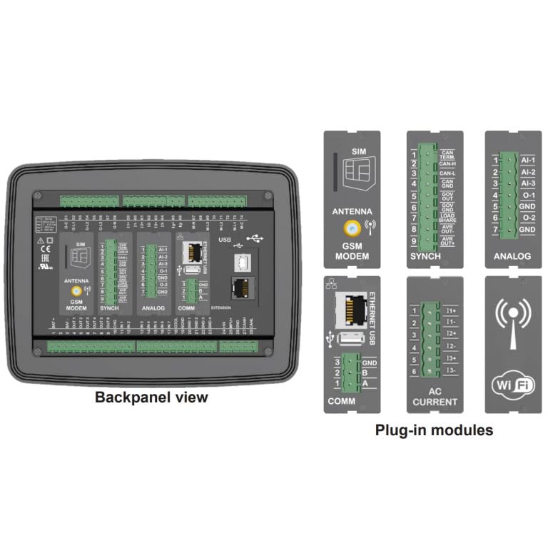
Figure 4.3.1: Back panel view of the D-500-MK3, highlighting the slots for various plug-in modules such as GSM modem, SYNCH, ANALOG, and COMM. Individual module examples like SIM, Antenna, Ethernet/USB, and AC Current are also shown, demonstrating the modular expansion capabilities.
4.4 PC Software and Communication
The D-500-MK3 can be configured and monitored using the Windows-based PC software. Connection can be established via USB, RS-485, Ethernet, or GPRS (with appropriate modules). The software allows for detailed parameter adjustments, event log review, and real-time data monitoring.
5. Operating the D-500-MK3
The D-500-MK3 features an intuitive front panel for local control and monitoring. The display provides real-time information on generator and mains parameters, while push buttons allow for mode selection and manual operations.
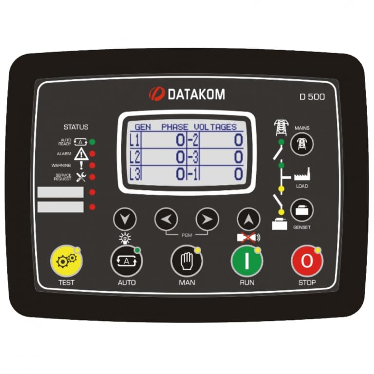
Figure 5.1.1: Front panel of the D-500-MK3 controller. This image displays the LCD screen showing generator phase voltages, status indicators (Auto, Ready, Alarm, Warning, Service Request), and control buttons for TEST, AUTO, MAN (Manual), RUN, and STOP, along with navigation buttons for menu interaction.
5.1 Front Panel Controls
- Display Screen: Shows various parameters such as generator phase voltages (L1, L2, L3), status indicators (Auto, Ready, Alarm, Warning, Service Request), and other operational data.
- Status Indicators: LEDs provide quick visual feedback on the controller's current state (e.g., Auto mode, Ready for operation, active Alarms, Warnings, or Service Requests).
- TEST Button: Initiates a test sequence for the generator.
- AUTO Button: Puts the controller into Automatic mode, enabling AMF/ATS functionalities and automatic start/stop based on configured parameters.
- MAN (Manual) Button: Switches to Manual mode, allowing direct control over generator start/stop and other functions.
- RUN Button: Manually starts the generator when in Manual mode.
- STOP Button: Manually stops the generator when in Manual mode.
- Navigation Buttons (Up, Down, Left, Right, Enter): Used to navigate through menus, adjust settings, and acknowledge alarms on the display.
5.2 Operational Modes
The D-500-MK3 supports several operational modes, configurable via the front panel or PC software:
- AMF (Automatic Mains Failure): Automatically starts the generator upon mains power failure and transfers load. Transfers back to mains and stops generator upon mains return.
- ATS (Automatic Transfer Switch): Manages power transfer between mains and generator, with options for uninterrupted transfer.
- Synchronization and Load Share: For multi-genset applications, the controller can synchronize multiple generators and share load among them or with the mains.
- Remote Start: Allows the generator to be started remotely via a signal input.
- Engine Control: Provides comprehensive control over engine parameters, including start/stop sequences, protection, and monitoring.
5.3 Remote Monitoring (Rainbow Scada)
The D-500-MK3 can be integrated with the Rainbow Scada web monitoring service, allowing users to monitor and control their gensets from any web browser. This requires appropriate communication modules (e.g., Ethernet or GPRS) to be installed and configured.
6. Maintenance
The D-500-MK3 is designed for robust and reliable operation with minimal maintenance. However, periodic checks are recommended to ensure optimal performance and longevity.
- Visual Inspection: Periodically inspect the controller for any signs of physical damage, loose connections, or dust accumulation.
- Cleaning: Keep the front panel and ventilation openings clean. Use a soft, dry cloth for cleaning. Do not use abrasive cleaners or solvents.
- Connection Integrity: Ensure all wiring connections to the terminals are secure and free from corrosion.
- Firmware Updates: Check the Datakom website periodically for available firmware updates to ensure your controller has the latest features and improvements. Updates can be performed via the USB port.
7. Troubleshooting
This section provides basic troubleshooting steps for common issues. For more complex problems, refer to the detailed technical manual or contact Datakom support.
| Problem | Possible Cause | Solution |
|---|---|---|
| Controller does not power on. | No power supply; incorrect wiring; blown fuse. | Check battery connections and voltage. Verify power supply wiring. Check for blown fuses in the power circuit. |
| Generator fails to start in AUTO mode. | Mains power present; start inhibit active; engine fault; low fuel. | Verify mains status. Check controller settings for start inhibits. Inspect engine for fuel, oil, and battery issues. Check alarm logs on the controller. |
| Communication issues (USB/Ethernet). | Incorrect cable; driver issues; network configuration; module not installed. | Ensure correct cable type and connection. Install necessary drivers for USB. Verify network settings (IP address, subnet mask). Confirm communication module is correctly installed. |
| Alarm indication on display. | Engine fault (e.g., high temperature, low oil pressure); sensor malfunction. | Note the specific alarm code/message. Refer to the detailed manual for alarm definitions. Address the underlying engine or sensor issue. |
Always ensure safety precautions are followed when troubleshooting electrical systems. If you are unsure, consult a qualified technician.
8. Specifications
The following are key specifications for the D-500-MK3 Multifunctional Generator Controller:
- Item Weight: 1.48 Pounds
- Manufacturer: DATAKOM
- ASIN: B0CNTFYN6J
- First Available: November 22, 2023
- Functionality: Multi genset synchronizer, load share, AMF, ATS, Remote Start, Engine Control, Remote Display Panel.
- Communication: USB, RS-485, Ethernet, GPRS (via plug-in modules).
- Engine Interface: MPU (Magnetic Pickup Unit), J1939 CAN bus.
- Expansion: Supports various plug-in modules for extended capabilities.
- Software: Windows-based PC software for configuration and monitoring; compatible with Rainbow Scada web service.
9. Warranty and Support
For specific warranty information regarding your D-500-MK3 controller, please refer to the documentation provided with your purchase or visit the official Datakom website. Datakom products are designed for industrial reliability and are backed by manufacturer support.
For technical assistance, troubleshooting beyond this manual, or inquiries about spare parts and accessories, please contact Datakom customer support or your authorized distributor. Ensure you have your product model number (D-500-MK3) and any relevant purchase details ready when contacting support.
Manufacturer: DATAKOM
Website: www.datakom.com.tr (Note: This is a placeholder URL, please refer to official documentation for the correct support contact information.)