1. Introduction
This manual provides detailed instructions for the installation, operation, and maintenance of the YUHANUS Electric Drop Bolt Lock. This lock is designed for use in door access control systems, featuring a fail-safe (NC) mode and an adjustable time delay function. Please read this manual thoroughly before installation and use to ensure proper function and safety.
2. Product Features
- NC Mode (Fail-Safe): The lock is in a locked state when power is applied. It unlocks when power is removed or when activated by a push button or remote controller.
- Time Delay Function: Adjustable delay settings of 0s, 3s, or 6s for unlocking.
- Versatile Application: Suitable for various door types including wooden, metal, and fireproof doors.
- Surface Mounted Design: Facilitates straightforward installation.
- Durable Construction: Made from aluminum for reliability.
3. Package Contents
Verify that all components are present before beginning installation:
- Electric Drop Bolt Lock Unit
- Faceplate/Panel Cover
- Mounting Screws
- Instruction Manual (this document)

Image 3.1: Contents of the YUHANUS Electric Drop Bolt Lock package, showing the main lock unit, mounting screws, and a printed instruction manual.
4. Specifications
| Specification | Value |
|---|---|
| Brand | YUHANUS |
| Model Name | Electric-Bolt-Lock01-NC |
| Model Number | 769894490594 |
| Lock Type | Deadbolt |
| Operating Voltage | DC 12V |
| Current | 200mA |
| Material | Aluminum |
| Item Dimensions (L x W x H) | 6 x 1.3 x 1 inches (150mm x 33mm x 27mm) |
| Special Feature | Auto-Lock, Time Delay (0s/3s/6s) |
| Control Method | Push Button, Remote (via access control system) |

Image 4.1: Detailed dimensions of the electric drop bolt lock, indicating measurements for length (150mm/5.91"), width (33mm/1.30"), and height (27mm/1.06").
5. Safety Information
- Ensure power is disconnected before installation or maintenance.
- This device operates on DC 12V. Incorrect voltage can damage the unit.
- All wiring should be performed by a qualified professional to prevent electrical hazards.
- Do not expose the lock to excessive moisture or extreme temperatures.
- Keep out of reach of children.
6. Installation
6.1 Mounting the Lock
- Identify the desired mounting location on the door frame and the corresponding strike plate location on the door. The lock is surface-mounted.
- Ensure sufficient clearance for the bolt to extend and retract freely.
- Mark the screw holes for the main lock unit and the strike plate.
- Drill pilot holes as necessary.
- Securely attach the main lock unit to the door frame and the strike plate to the door using the provided screws.
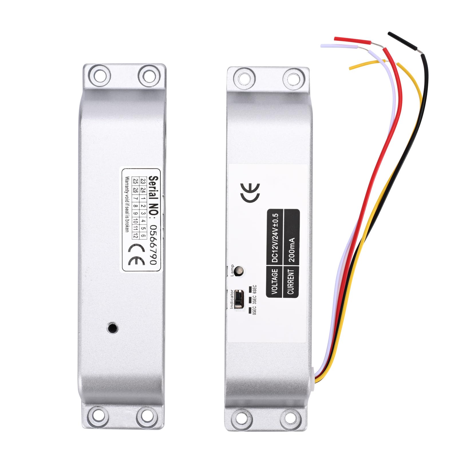
Image 6.1: The main electric drop bolt lock unit and its corresponding strike plate, ready for installation.

Image 6.2: An example installation of the electric drop bolt lock on a glass door, demonstrating its integration with an access control keypad and exit button.
6.2 Wiring Diagram
Connect the lock to your access control system according to the following diagram. Pay close attention to polarity.
- Red Cable: Connect to +12V (positive power supply).
- Black Cable: Connect to GND (ground/negative power supply).

Image 6.3: Detailed wiring diagram illustrating how to connect the electric bolt lock to an access control keypad, power supply, and exit switch button. The red cable connects to +12V and the black cable to GND.
7. Operating Instructions
7.1 NC Mode (Fail-Safe) Operation
In NC (Normally Closed) mode, the lock is engaged and secures the door when power is supplied. To unlock the door, the power to the lock must be temporarily interrupted or a signal from an access control device (e.g., push button, remote controller, keypad) must be received to release the bolt.
7.2 Time Delay Function
The lock features an adjustable time delay for unlocking. This delay can be set to 0 seconds, 3 seconds, or 6 seconds. This function allows for a brief period before the door can be opened after an unlock signal is received, which can be useful in certain access control scenarios.
To adjust the time delay:
- Locate the small switch or jumper settings on the side of the lock unit, typically labeled '0SEC', '3SEC', '6SEC'.
- Use a small tool (e.g., screwdriver) to set the switch to the desired delay time.

Image 7.1: A detailed view of the lock's indicator and time delay setting switch, allowing selection between 0, 3, and 6 seconds.
8. Maintenance
- Regularly inspect the lock and strike plate for any signs of wear or damage.
- Keep the lock mechanism clean and free from dust and debris.
- Ensure all wiring connections remain secure.
- Do not lubricate the internal mechanism unless specifically instructed by the manufacturer.
9. Troubleshooting
| Problem | Possible Cause | Solution |
|---|---|---|
| Lock does not engage (stay locked) | No power or insufficient power supply. Incorrect wiring. Faulty lock unit. | Check power supply (DC 12V). Verify wiring connections (Red to +12V, Black to GND). Test with a known good power supply. If problem persists, contact support. |
| Lock does not disengage (unlock) | No unlock signal from access control. Incorrect wiring. Mechanical obstruction. | Ensure access control system is sending an unlock signal. Check wiring for the unlock signal. Inspect for any physical obstructions preventing the bolt from retracting. |
| Time delay not functioning correctly | Incorrect time delay setting. | Verify the time delay switch setting on the lock unit (0s, 3s, or 6s). |
10. Warranty and Support
For warranty information or technical support, please contact YUHANUS customer service through your purchase platform or the official YUHANUS website. Please have your model number (Electric-Bolt-Lock01-NC) and purchase date available when contacting support.


