1. Introduction
This manual provides essential information for the safe and effective use of your Schneider Electric Thorsman Analogue Multimeter IMT23113. Please read these instructions carefully before operation and retain them for future reference.
The IMT23113 is a traditional analogue multimeter designed for measuring DC voltage, DC current, resistance, decibels, and continuity. It also features a battery test function for common battery types.

Figure 1.1: Schneider Electric Thorsman Analogue Multimeter IMT23113 in its packaging.
This image displays the multimeter sealed in its clear plastic retail packaging, highlighting its green and grey color scheme and the 'Life Is On Schneider Electric' branding.
2. Safety Information
Always observe standard safety precautions when using electrical testing equipment. This device is rated CAT III, 300 V, indicating its suitability for measurements in building installation applications.
- Do not exceed the maximum input values for any range.
- Ensure the test leads are in good condition, free from cracks or damage.
- Always select the appropriate function and range before making a measurement.
- Disconnect power to the circuit before measuring resistance or continuity.
- Do not use the multimeter if it appears damaged or is operating abnormally.
- Replace the fuse only with one of the specified type and rating (500 mA).
3. Setup and Initial Use
3.1 Unboxing and Included Components
Upon opening the package, verify that all components are present:
- Schneider Electric Thorsman Analogue Multimeter IMT23113
- Instruction Leaflet
- 1 x 1.5V AA Battery (included)
3.2 Battery Installation
The multimeter requires one 1.5V AA battery for operation. To install or replace the battery:
- Locate the green protective holster around the meter.
- Gently pull the black plastic meter section upwards while simultaneously bending the edges of the green holster outwards. The meter and holster are separate components, though they may initially appear as one sealed unit.
- Once separated, the battery compartment cover will be accessible on the rear of the meter.
- Unscrew the battery compartment cover and insert the 1.5V AA battery, observing the correct polarity (+/-).
- Replace the cover and reassemble the meter into its holster.

Figure 3.1: Rear view showing the battery compartment access.
This image shows the back of the multimeter with the green holster partially removed, revealing the black battery compartment cover and the screw for access.
3.3 Connecting Test Leads
The multimeter comes with integrated test leads. The red lead is for positive (+) connections and the black lead is for negative (-) or common connections. Ensure the leads are securely connected to the appropriate input jacks on the meter.

Figure 3.2: Front view of the multimeter with test leads.
This image provides a clear view of the front panel of the multimeter, showing the analogue display, the rotary selector switch, and the red and black test leads plugged into their respective ports at the bottom.
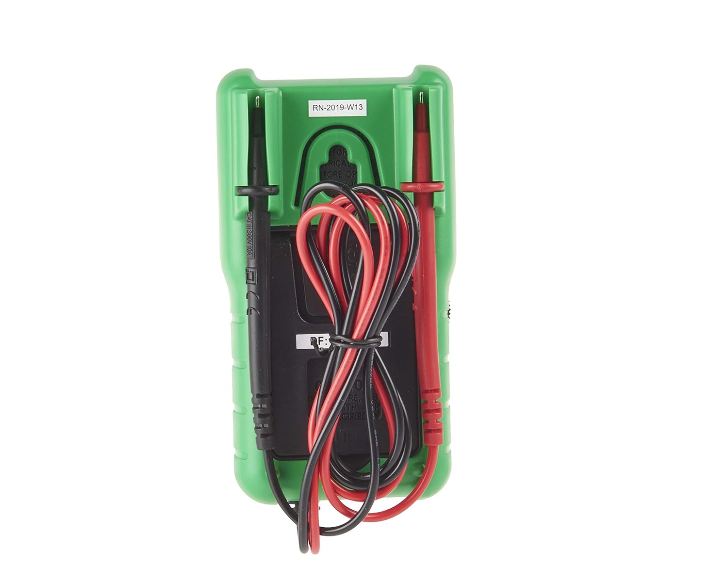
Figure 3.3: Rear view showing test lead storage.
This image shows the back of the multimeter, demonstrating how the test leads can be neatly stored by wrapping them around the meter and securing the probes in designated slots on the back of the green holster.
4. Operating Instructions
4.1 General Operation
The multimeter does not feature a dedicated On/Off switch. It is activated by selecting a measurement function using the rotary switch. To conserve battery life, always return the rotary switch to the 'OFF' position (typically indicated by a dot or a specific range that draws minimal power) when not in use, or remove the battery for extended storage.
Before taking any measurement, ensure the meter's needle is at the zero mark. If not, use the '0 Ω ADJ' knob to calibrate the needle to zero for resistance measurements, or the mechanical zero adjustment screw for other ranges if necessary.
4.2 Measurement Functions
Use the central rotary switch to select the desired measurement function and range:
- DC Voltage (V=): Ranges include 12V, 60V, 120V, and 300V. Connect the red lead to the positive side of the circuit and the black lead to the negative side.
- DC Current (mA=): Ranges include 0.6mA, 12mA, and 600mA. Connect the multimeter in series with the circuit.
- Resistance (Ω): Ranges include x10 Ω and x1 kΩ. Before measuring, short the test leads together and adjust the '0 Ω ADJ' knob until the needle reads zero on the resistance scale. Disconnect power from the circuit before measuring resistance.
- Decibel (dB): Range -20 to 23 dB. Used in conjunction with AC voltage measurements.
- Continuity: Indicates continuity for resistances under 20 Ω. The meter will show a low resistance reading.
- Battery Test (BATT): Dedicated settings for 1.5V (AA, AAA, and button cell) and 9V batteries. Connect the battery to the test leads. The needle will indicate the battery's condition on a specific scale, often marked with 'Good' (green) and 'Replace' (red) sections.
5. Maintenance
5.1 Cleaning
Clean the multimeter with a soft, damp cloth. Do not use abrasive cleaners or solvents. Ensure the device is dry before storage or next use.
5.2 Fuse Replacement
The multimeter is fused by a 500 mA fuse. If the current measurement function ceases to work, the fuse may need replacement. Refer to the battery installation section for accessing the internal components. Always replace with a fuse of the exact same type and rating.
5.3 Battery Replacement
Refer to Section 3.2 for detailed instructions on battery replacement. Replace the battery when the meter's readings become erratic or the needle does not respond correctly.
5.4 Test Lead Care
Inspect test leads regularly for any signs of wear, cuts, or damage. While the leads are integrated, ensuring their integrity is crucial for safe and accurate measurements. Some users have observed that the metal tips of the probes are relatively short; exercise care when making connections to ensure proper contact.
6. Troubleshooting
- Meter does not respond: Check if the battery is correctly installed and has sufficient charge. Ensure the rotary switch is set to a measurement range and not in an 'OFF' or storage position.
- Inaccurate readings: Verify that the correct measurement range has been selected. For resistance measurements, ensure the '0 Ω ADJ' knob has been calibrated. Check for proper contact of the test leads with the circuit.
- No current measurement: The 500 mA fuse may be blown. Replace it as per Section 5.2.
- Needle not at zero: For resistance measurements, use the '0 Ω ADJ' knob. For other ranges, a small mechanical adjustment screw near the needle pivot may be present for fine-tuning the mechanical zero.
7. Specifications
| Attribute | Value |
|---|---|
| Manufacturer | Schneider Electric |
| Part Number | IMT23113 |
| Item Model Number | IMT23113 |
| Product Dimensions | 14 x 7.5 x 5 cm |
| Item Weight | 352 g |
| Colour | Green/Grey |
| Style | Plain |
| Power Source Type | Battery Powered |
| Voltage | 300 Volts (CAT III) |
| Batteries Required | 1 x 1.5V AA (included) |
| Battery Cell Type | Alkaline |
| DC Voltage Range | 12V, 60V, 120V, 300V |
| DC Current Range | 0.6mA, 12mA, 600mA |
| Resistance Range | x10 Ω, x1 kΩ |
| Decibel Range | -20 to 23 dB |
| Continuity Test | Under 20 Ω |
| Battery Test | 1.5V (AA, AAA, button cell), 9V |
| Fuse | 500 mA |
| Electrical Insulation | CAT III, 300 V |
8. Warranty and Support
Warranty information for your Schneider Electric Thorsman Analogue Multimeter IMT23113 is typically provided with the product at the time of purchase or can be found on the official Schneider Electric website. Please refer to these resources for details regarding warranty coverage and terms.
For technical support, product inquiries, or service, please contact Schneider Electric customer service through their official channels. Contact information can usually be found on the manufacturer's website or in the product packaging.


