
1. Introduction
The Micsig VTO Series VTO 2004 is a high-performance oscilloscope designed for precise signal test and measurement. This device offers a 200MHz bandwidth, 1GSa/s sampling rate, and 50Mpts memory depth, making it suitable for a wide range of applications. Its compact design and versatile connectivity options provide a new experience in portable measurement.

Figure 1.1: Micsig VTO 2004 Oscilloscope connected to a tablet.
2. Safety Precautions
To ensure safe operation and prevent damage to the product or other equipment, please read and follow all safety instructions carefully. Observe all warnings and cautions marked on the product and in this manual.
- Do not perform floating measurements.
- Do not attempt to repair or modify the product by yourself.
- To avoid fire and overcurrent shock, please review all ratings prior to connecting the product.
- Ensure proper ventilation; do not block ventilation openings.
- Use only the original battery (if applicable) and power adapter provided.
- Always switch the power lock to "OFF" after oscilloscope shut down to prevent accidental turn-on.

Figure 2.1: Excerpt from the safety precautions section of the manual.
3. Package Contents
Verify that all items listed below are included in your product package. If any items are missing or damaged, please contact Micsig customer support.
- Micsig VTO 2004 Oscilloscope Unit
- Power Adapter
- USB-C Cable
- Test Leads (various types, e.g., BNC to alligator clips, test probes)
- User Manual / Calibration Certificate
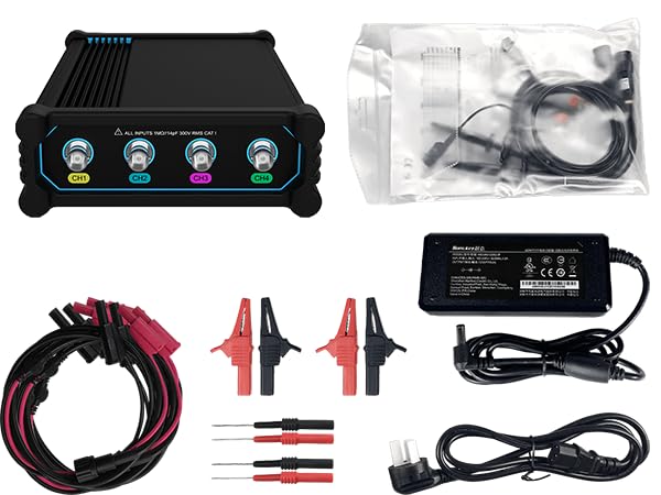
Figure 3.1: Micsig VTO 2004 Oscilloscope and included accessories.
Video 3.1: Unboxing the Micsig VTO 2004 Oscilloscope and its contents.
4. Product Overview and Interfaces
The Micsig VTO 2004 features a robust design with clearly labeled interfaces for ease of use.

Figure 4.1: Front and Rear Panel Interfaces.
Front Panel:
- CH1, CH2, CH3, CH4: BNC input channels for connecting probes.
Rear Panel:
- POWER LOCK: Slide switch to enable/disable power.
- Power Button: Press to turn the unit on/off.
- DC 12V-24V: DC power input for the adapter.
- Wire Rack: For cable management.
- Charging Port: For charging the internal battery.
- USB-C: For data transfer and connection to Android devices.
- Probe Calibration Output: For calibrating oscilloscope probes.
5. Setup
- Charge the Battery: Connect the provided power adapter to the DC input port and a power outlet. The internal 7500mAh Lithium-ion battery will begin charging.
- Connect to a Device: Use the USB-C cable to connect the oscilloscope unit to a compatible Android tablet or device.
- Install Software: Download and install the Micsig oscilloscope application on your Android device. Refer to the quick start guide for QR codes or links.
- Power On: Slide the POWER LOCK switch to the left (unlocked position), then press the Power Button to turn on the oscilloscope unit.
- Connect Probes: Attach the desired test probes or leads to the BNC input channels (CH1-CH4) on the front panel.

Figure 5.1: Typical setup with the oscilloscope unit and a connected tablet.
6. Operating Instructions
The Micsig VTO 2004 is operated primarily through the dedicated Android application on your connected device. This section provides general guidance.
6.1 Basic Measurement
- Ensure the oscilloscope unit is powered on and connected to your Android device.
- Launch the Micsig oscilloscope application.
- Connect the probes to the circuit or signal you wish to measure.
- Adjust the vertical scale (Volts/Div) and horizontal scale (Time/Div) within the application to properly display the waveform.
- Use the trigger settings to stabilize the waveform for clear observation.
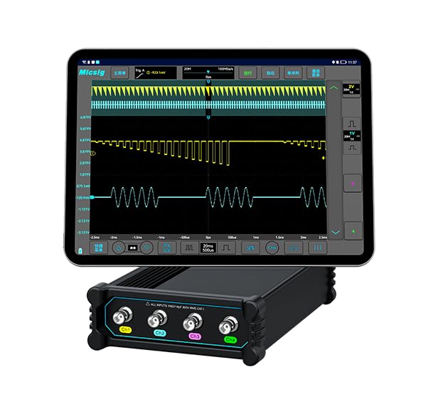
Figure 6.1: Waveform display on the Micsig oscilloscope application.
6.2 Advanced Features
- Serial Bus Decode: The VTO 2004 supports CAN and LIN serial bus decoding. Access this feature through the application's analysis menu.
- Auto Measurements: Perform up to 31 types of automated measurements (e.g., Vpp, Vmax, Frequency, Period) with a single tap.
- Memory Depth: Utilize the 50Mpts memory depth for capturing long signal sequences or detailed transient events.

Figure 6.2: Oscilloscope in an automotive diagnostic application.
7. Maintenance
Proper maintenance ensures the longevity and accuracy of your Micsig VTO 2004 Oscilloscope.
- Cleaning: Use a soft, damp cloth to clean the exterior of the unit. Do not use abrasive cleaners or solvents.
- Storage: Store the device in a cool, dry environment away from direct sunlight and extreme temperatures.
- Battery Care: If storing for extended periods, ensure the battery is partially charged (around 50%) to prolong its lifespan.
- Software Updates: Regularly check for and install software updates for the Android application to ensure optimal performance and access to new features.
8. Troubleshooting
This section addresses common issues you might encounter with your Micsig VTO 2004 Oscilloscope.
8.1 No Power
- Ensure the POWER LOCK switch is in the unlocked position.
- Verify the power adapter is securely connected to both the unit and a working power outlet.
- Check if the battery is charged.
8.2 No Waveform Display
- Confirm the USB-C connection between the oscilloscope unit and the Android device is secure.
- Ensure the Micsig application is running and properly connected to the unit.
- Check probe connections to the BNC input channels and the circuit under test.
- Adjust the vertical (Volts/Div) and horizontal (Time/Div) scales in the application.
- Verify trigger settings are appropriate for the signal being measured.
8.3 Inaccurate Measurements
- Perform probe calibration using the dedicated output on the rear panel.
- Ensure probes are correctly compensated for the input impedance.
- Check for proper grounding of the oscilloscope and the circuit under test.
9. Specifications
Key technical specifications for the Micsig VTO 2004 Oscilloscope.
| Feature | Specification |
|---|---|
| Model | VTO2004 |
| Bandwidth | 200MHz |
| Analog Channels | 4 |
| Rise Time | ≤1.8ns |
| Sampling Rate | 1GSa/s |
| Memory Depth | 50Mpts |
| DC Gain Accuracy | ≤ 2% |
| Input Impedance | 1MΩ±1% || 14pF |
| Interface | USB Type-C, DC power |
| Optional Battery | 7.4V, 7500mAh Lithium-ion battery |
| Dimensions | 140*215*52mm |
| Net Weight | 640g |

Figure 9.1: Product Specifications Table.
10. Warranty and Support
Micsig Technology Co., Ltd. provides warranty and technical support for its products. For detailed warranty information, please refer to the warranty card included in your package or visit the official Micsig website. For technical assistance, troubleshooting, or service inquiries, please contact Micsig customer support directly.
Manufacturer: Micsig Technology Co., Ltd
Date First Available: November 10, 2023