1. Introduction
This manual provides essential information for the installation, operation, and maintenance of the PHOENIX CONTACT FL WLAN 4321 Wireless Ethernet Bridge, model 1194423. This pre-paired wireless bridge system is designed to extend Ethernet networks wirelessly over distances up to 2 miles, offering a reliable 300 Mbps connection. It utilizes Passive POE for simplified power and data transmission.
2. Product Overview
The FL WLAN 4321 system consists of two pre-configured wireless Ethernet bridge units, enabling a point-to-point wireless connection. These units are ideal for applications requiring robust and long-range network extension without the need for complex cabling. The Passive POE capability allows for flexible installation by delivering power and data over a single Ethernet cable.
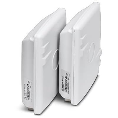
Figure 2.1: The PHOENIX CONTACT FL WLAN 4321 Wireless Ethernet Bridge units. The image displays two identical white rectangular devices, positioned vertically next to each other. Each unit has a label on its side, indicating "FL WLAN 4321" and a letter (A or B) for identification.
3. Package Contents
Verify that all items are present and in good condition upon unpacking:
- 2 x PHOENIX CONTACT FL WLAN 4321 Wireless Ethernet Bridge Units (Pre-paired)
- 2 x Passive Power over Ethernet (POE) Injectors
- 2 x Power Cords for POE Injectors
- 1 x Quick Start Guide
4. Safety Information
Observe the following safety precautions to prevent damage to the device or injury to personnel:
- Ensure proper grounding for all electrical connections.
- Do not expose the device to extreme temperatures, humidity, or direct sunlight.
- Avoid placing the device near strong electromagnetic fields.
- Only use the provided power adapters and cables.
- Installation should be performed by qualified personnel in accordance with local electrical codes.
5. Setup
The FL WLAN 4321 units are pre-paired for ease of installation. Follow these steps for initial setup:
- Identify Units: Unpack both bridge units. They are typically labeled 'A' and 'B' or similar for easy identification of the master and client roles, though they are pre-paired to function together.
- Mounting: Choose suitable mounting locations for each unit. For optimal performance, ensure a clear line of sight between the two units. Mount them securely using appropriate hardware (not included).
- Connect Ethernet Cables:
- Connect one end of an Ethernet cable from your network device (e.g., router, switch) to the "LAN" port on the Passive POE Injector.
- Connect the other end of the Ethernet cable from the "POE" port on the Passive POE Injector to the Ethernet port on the Wireless Ethernet Bridge unit.
- Connect Power: Plug the power cord into the Passive POE Injector and then into a suitable power outlet. The bridge unit will power on via the Ethernet cable.
- Verify Connection: Once both units are powered on and connected, observe the LED indicators. A solid link LED on both units typically indicates a successful wireless connection between them. Refer to the "Operating Instructions" section for LED status meanings.
- Network Configuration: Ensure your network devices connected to the bridges are configured correctly (e.g., IP addresses, subnet masks) to communicate across the wireless link.
6. Operating Instructions
Once installed and powered, the FL WLAN 4321 units operate automatically as a transparent wireless Ethernet bridge. Data transmitted on one side of the bridge will be wirelessly relayed to the other side.
LED Indicators:
| LED Name | Status | Description |
|---|---|---|
| Power LED | Solid Green | Device is powered on. |
| LAN LED | Solid Green | Ethernet link established. |
| LAN LED | Flashing Green | Data activity on Ethernet port. |
| WLAN LED | Solid Green | Wireless link established between units. |
| WLAN LED | Flashing Green | Data activity over wireless link. |
7. Maintenance
Regular maintenance helps ensure the longevity and optimal performance of your wireless Ethernet bridge.
- Cleaning: Gently wipe the exterior of the units with a soft, dry cloth. Do not use liquid cleaners or aerosols.
- Firmware Updates: Periodically check the PHOENIX CONTACT website for available firmware updates. Applying updates can improve performance, add features, or address security vulnerabilities. Follow the instructions provided with the firmware update package carefully.
- Environmental Check: Ensure the operating environment remains within specified temperature and humidity ranges. Keep the area around the units clear to allow for proper ventilation.
8. Troubleshooting
If you encounter issues with your FL WLAN 4321 system, refer to the following common problems and solutions:
| Problem | Possible Cause | Solution |
|---|---|---|
| No Power (Power LED Off) | No power from POE injector or power outlet. | Check power cord connection to POE injector and wall outlet. Ensure the POE injector is functioning. Verify Ethernet cable from POE injector to bridge unit is securely connected. |
| No Wireless Link (WLAN LED Off) | No line of sight, excessive distance, interference, or unit malfunction. | Ensure clear line of sight between units. Reduce distance if possible. Check for sources of interference (e.g., large metal objects, other wireless devices). Power cycle both units. |
| No Ethernet Link (LAN LED Off) | Faulty Ethernet cable or connected device. | Verify Ethernet cable connection to the bridge unit and the connected network device. Try a different Ethernet cable. Test the connected network device. |
| Slow Connection Speed | Interference, signal degradation, or network congestion. | Optimize unit placement for better signal strength. Minimize sources of interference. Check for network congestion on your wired network. |
9. Specifications
| Attribute | Detail |
|---|---|
| Model Number | 1194423 |
| Brand | PHOENIX CONTACT |
| Type | Wireless Ethernet Bridge (Pre-paired) |
| Connectivity | Wireless, Ethernet |
| Power Method | Passive POE |
| Max Data Rate | 300 Mbps |
| Max Range | 2 miles (approx. 3.2 km) |
| ASIN | B0CMZCD3W6 |
| Manufacturer | Phoenix Contact |
| First Available Date | November 8, 2023 |
10. Warranty Information
PHOENIX CONTACT products are manufactured to the highest quality standards. This product is covered by the manufacturer's standard warranty. For detailed information regarding warranty terms, conditions, and duration, please refer to the official PHOENIX CONTACT website or contact their customer support directly. Keep your proof of purchase for warranty claims.
11. Support Information
For technical assistance, product inquiries, or further support, please contact PHOENIX CONTACT through their official channels:
- Website: Visit the official PHOENIX CONTACT website for product documentation, FAQs, and support resources. www.phoenixcontact.com
- Customer Service: Refer to the contact section on their website for phone numbers or email support.


