Introduction
The DROK DC-DC Buck Converter is a high-quality power module designed for reliable power supply across a wide range of electronic devices and projects. It features excellent performance, versatility, and multiple protection functions to ensure safe and stable operation. This manual provides detailed instructions for its setup, operation, and maintenance.
Safety Precautions
- Always ensure correct wiring before applying power. Incorrect connections can damage the module or connected devices.
- Do not exceed the specified input voltage, output voltage, or current limits.
- Operate the module in a well-ventilated area to prevent overheating.
- Avoid touching the module components while it is powered on, as some parts may become hot.
- If the output voltage cannot be set or there is no response when connected to the power supply, check the wiring for errors.
Product Features
- Digital Control: Precise adjustment of output voltage and current.
- Wide Input/Output Range: Input 6-70V, Output 0-60V.
- High Power Output: Up to 20A and 1200W.
- Multiple Protection Functions: Includes input undervoltage protection (LVP), output overvoltage protection (OVP), output overcurrent protection (OCP), overpower protection, and overtemperature protection.
- High-Quality Construction: Utilizes high-quality power devices and precision operational amplifiers for stable performance.
- Efficient Heat Dissipation: Built-in smart temperature-controlled cooling fan and external protection MOSFETs.
- LCD Display: Clear display of output status, voltage, current, power, capacity, energy, and time.
- User-Friendly Interface: Easy parameter adjustment via buttons and encoder.
Product Components and Dimensions
Familiarize yourself with the various components of the buck converter module.

Image: Module Component Diagram. This diagram illustrates the main parts of the buck converter, including the smart temperature control fan, heat dissipation fins, input/output terminals (positive and negative), 10K NTC external temperature sensor interface, DIP switches for fixed voltage settings, button connection terminal, display connection terminal, and power switch.

Image: Product Dimensions. This image provides the physical dimensions of the main converter board (110mm x 73mm x 50mm) and the separate display unit (79mm x 43mm x 26mm).
Key Components:
- Input Terminals: For connecting the DC input power source (6-70V).
- Output Terminals: For connecting the load (0-60V).
- Power Switch: To turn the module on/off.
- Cooling Fan: Smart temperature-controlled fan for heat dissipation.
- DIP Switches: Used for setting fixed output voltages when the module is used as a standalone board.
- Encoder Button: For adjusting parameters and navigating display modes.
- SW Button: For switching display parameters.
- LCD Display: Shows real-time voltage, current, power, and other parameters.
Specifications

Image: Product Specifications. This table details the electrical and operational characteristics of the buck converter.
| Parameter | Value |
|---|---|
| Input Voltage | 6.0V to 70V |
| Output Voltage | 0.0V to 60V |
| Output Current | 20A (Max) |
| Output Power | 0W to 1200W (Max) |
| Input Protection | Overvoltage Protection, Undervoltage Protection |
| Output Protection | Overvoltage Protection, Overcurrent Protection, Overpower Protection, Overtemperature Protection |
| Voltage Measurement Resolution | 0.01V |
| Current Setting Resolution | 0.01A |
| Typical Output Ripple | 100mV VPP |
| Cooling Fan ON Condition | Current > 2A, Power > 50W, Temperature > 50°C |
| Cooling Fan OFF Condition | Current < 1.5A, Power < 45W, Temperature < 45°C |
Setup and Installation
1. Wiring Connections
- Connect your DC input power source (6-70V) to the Input Positive (+) and Input Negative (-) terminals.
- Connect your load to the Output Positive (+) and Output Negative (-) terminals.
- Ensure all connections are secure and correct before applying power.
2. DIP Switch Settings for Fixed Output Voltage
The module features DIP switches for setting specific fixed output voltages when used as a standalone board. This is useful for applications requiring a constant, predefined voltage without digital adjustment.
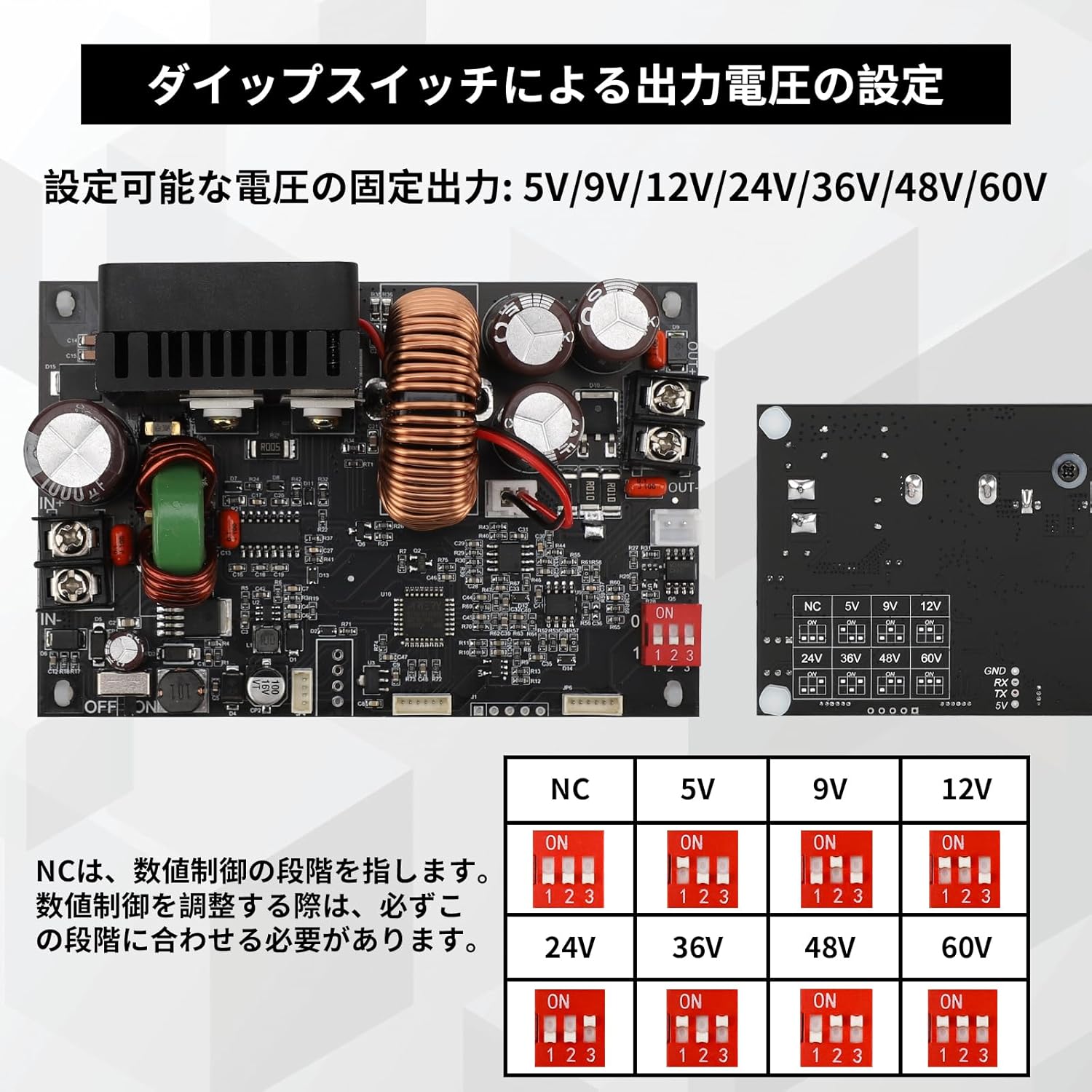
Image: DIP Switch Settings. This diagram illustrates how to configure the DIP switches to achieve fixed output voltages such as 5V, 9V, 12V, 24V, 36V, 48V, and 60V. 'NC' refers to the digital control stage, which should be matched when adjusting digital control.
Refer to the diagram above to set the desired fixed output voltage. Ensure the module is powered off before changing DIP switch settings.
Operating Instructions
1. Power On/Off
- Toggle the power switch to turn the module ON or OFF.
2. Adjusting Output Voltage and Current
- Use the encoder button (rotary knob) to adjust the output voltage and current. Rotate clockwise to increase, counter-clockwise to decrease.
- Press the encoder button briefly to switch between adjusting voltage and current.
3. LCD Display Modes
The LCD provides real-time monitoring of various parameters.

Image: Multimeter Display. This image shows the LCD display in various states: when power is ON, displaying constant voltage (CV) mode with output voltage and current; when the encoder button is short-pressed, cycling through power (W), capacity (AH), energy (WH), and time (H); and when power is OFF, sequentially displaying the set voltage and current.
- When Power is ON: The display shows output voltage and output current. It also indicates Constant Voltage (CV) or Constant Current (CC) mode.
- Short Press Encoder Button: On the operating screen, a short press of the encoder button will cycle through displaying Power (W), Capacity (AH), Energy (WH), and Time (H).
- When Power is OFF: The display will sequentially show the previously set voltage and current values.
- SW Button: Use the SW button to switch between different display parameters or settings.
Maintenance
- Keep the module clean and free from dust. Use a soft, dry cloth for cleaning.
- Ensure proper airflow around the module, especially the cooling fan, to maintain optimal heat dissipation.
- Regularly check wiring connections for tightness and signs of wear.
- Store the module in a dry, cool environment when not in use.
Troubleshooting
- No Output Voltage / No Response: If the output voltage cannot be set or the module does not respond when connected to power, check all wiring connections carefully. Ensure input voltage is within the specified range (6-70V). Incorrect wiring is a common cause.
- Overheating: If the module becomes excessively hot, ensure it is operating within its specified current and power limits. Verify that the cooling fan is functioning correctly and that there is adequate ventilation.
- Protection Triggered: If the module shuts down unexpectedly, one of the protection functions (OVP, OCP, OPP, OTP, LVP) may have been triggered. Check your load and input power source to ensure they are within safe operating parameters.
- Inaccurate Readings: If the voltage or current readings appear inaccurate, ensure proper calibration (if applicable, though this module is digitally controlled for precision). Verify your multimeter for comparison.
For persistent issues, please contact DROK customer support for assistance.
Applications
The DROK DC-DC Buck Converter is suitable for a variety of applications due to its precise control and robust protection features.

Image: Application Scenarios. This image showcases typical environments where the buck converter can be utilized, including laboratory and research settings, electronic device repair, industrial automation and testing, and educational training.
- DIY Projects: Ideal for custom power supply needs in hobbyist electronics.
- Electronics Experiments: Provides a stable and adjustable power source for testing circuits.
- Research and Development: Useful in laboratory settings for various power requirements.
- Electronic Device Repair: Can be used as a versatile power source for diagnosing and repairing devices.
- Industrial Automation and Testing: Suitable for providing controlled power in industrial applications.
- Educational Training: An excellent tool for teaching power electronics concepts.
Warranty and Support
DROK products are designed for reliability and performance. For warranty information, technical support, or any questions regarding the operation of your DC-DC Buck Converter, please refer to the contact information provided with your purchase or visit the official DROK website. Our support team is available to assist you with any issues or inquiries.


