1. Introduction
This manual provides detailed instructions for the safe and effective operation of the SULMILE ETCR3100C Soil Resistivity and Earth Resistance Tester. The ETCR3100C is a high-precision digital instrument designed for measuring earth resistance, soil resistivity, and earth voltage. It supports 2-wire, 3-wire, and 4-wire measurement methods, incorporating advanced FFT (Fast Fourier Transform) and AFC (Automatic Frequency Control) technologies for enhanced accuracy and anti-interference capabilities. Please read this manual thoroughly before using the device to ensure proper functionality and safety.
2. Safety Information
Always adhere to the following safety guidelines to prevent injury or damage to the instrument:
- Do not operate the tester in explosive atmospheres or in the presence of flammable gases or dust.
- Ensure all test leads are securely connected before performing any measurements.
- Avoid touching the test electrodes or terminals during measurement to prevent electric shock.
- Verify that the earth voltage is within the specified range (AC 0-600V) before testing.
- The instrument is rated IP65 for protection against dust and water jets; however, avoid submerging it in water.
- Use only the provided charger and battery. Improper charging can lead to fire or explosion.
- If the instrument shows signs of damage, do not use it. Contact qualified service personnel.
3. Product Overview
3.1 Components
The SULMILE ETCR3100C tester features a robust design with clearly labeled components for ease of use. Refer to the diagram below for an identification of the main parts.

Figure 1: Main Components of the ETCR3100C Tester
- Instrument Body: The main housing of the device.
- Liquid Display LCD: Large screen with white backlight for displaying measurement results and settings.
- Function Gear Knob: Used to select measurement modes (Earth Resistance, Soil Resistivity, Earth Voltage) and power the device on/off.
- Function Key Area: Contains buttons for TEST, HOLD, SET, ALARM, CLEAR, and READ functions.
- Input Terminals (E, ES, P, C): Color-coded terminals for connecting test leads for various measurement configurations.
- USB Interface: For connecting the tester to a computer for data transfer.
- Charging Interface: For connecting the power adapter to recharge the internal battery.
- Host Shell: The protective outer casing, designed for durability.
- Wiring Diagram: Located on the inside of the lid, providing quick reference for test lead connections.
3.2 Key Features
The ETCR3100C offers a range of features designed for professional use:
- Advanced Multi-Method Testing: Supports 2-wire, 3-wire, and 4-wire earth resistance measurements with FFT and AFC technologies for high accuracy and interference immunity.
- Versatile Measurement Functions: Capable of measuring earth resistance (0.00Ω-30.00kΩ), soil resistivity (0.00Ωm-9000kΩm), and earth voltage (AC 0V-600V).
- User-Friendly LCD Display: Large screen with white backlight, bar chart indication, and adjustable alarm function for efficient monitoring.
- Robust & Portable Design: Housed in an IP65-rated protective case, making it shock-resistant, fall-resistant, and suitable for outdoor environments. Features a high-capacity rechargeable lithium battery.
- Data Storage & USB Connectivity: Stores up to 300 sets of data and supports USB data upload for historical query, real-time monitoring, and report generation.
4. Setup
4.1 Unpacking and Contents Verification
Carefully unpack the ETCR3100C tester and all accessories. Verify that all items listed below are present and undamaged.
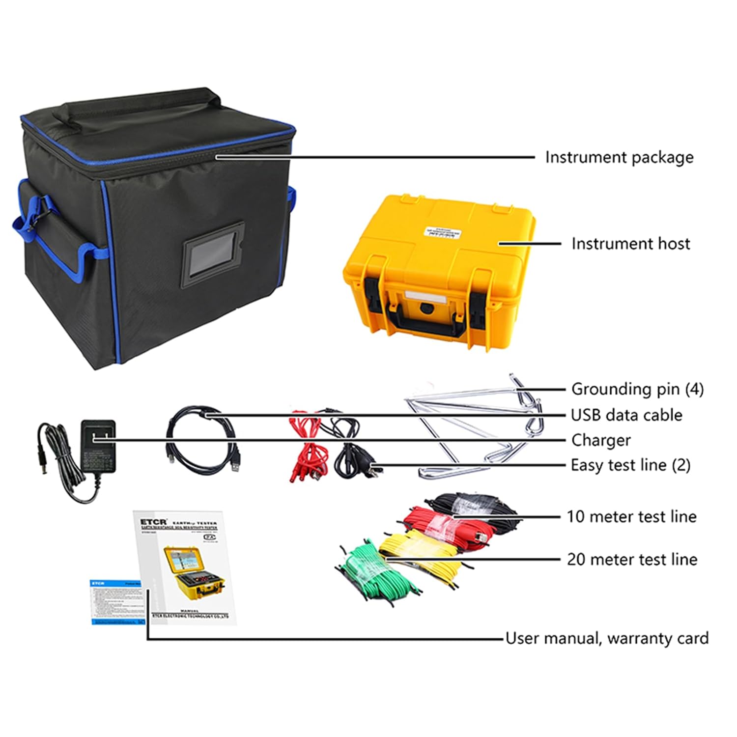
Figure 2: Package Contents
- ETCR3100C Earth Resistance Soil Resistivity Tester
- Instrument Package (Carrying Bag)
- Grounding Pins (4)
- USB Data Cable
- Charger
- Easy Test Line (2)
- 10 Meter Test Line
- 20 Meter Test Line
- User Manual
- Warranty Card
4.2 Charging the Battery
The ETCR3100C is equipped with a high-capacity rechargeable lithium battery. Before first use, or if the battery indicator is low, connect the provided charger to the charging interface on the instrument and plug it into a suitable power outlet. The charging indicator will show the charging status. Ensure the device is powered off during charging for optimal battery life.
4.3 Connecting Test Leads
Proper connection of test leads is crucial for accurate measurements. Refer to the wiring diagrams provided on the inside of the tester's lid or in the relevant section of this manual for specific measurement configurations.

Figure 3: Tester with Wiring Diagrams
The terminals are labeled as follows:
- E (Earth): Main earth electrode connection.
- ES (Auxiliary Earth): Auxiliary earth electrode connection, often used for 4-wire measurements.
- P (Potential): Potential electrode connection.
- C (Current): Current electrode connection.
5. Operating Instructions
5.1 Power On/Off
To power on the device, rotate the Function Gear Knob from the 'OFF' position to the desired measurement mode (e.g., R_EARTH, P_EARTH, V_EARTH). To power off, rotate the knob back to 'OFF'.
5.2 Measurement Modes
The ETCR3100C supports three primary measurement functions:
5.2.1 Earth Resistance (R_EARTH)
This mode measures the resistance of grounding systems. The tester supports 2-wire, 3-wire, and 4-wire methods. The 4-wire method offers the highest accuracy by eliminating the resistance of the test leads.
- Rotate the Function Gear Knob to the 'R_EARTH' position.
- Connect the test leads and grounding pins according to the specific wiring diagram for your chosen method (2-wire, 3-wire, or 4-wire). Refer to the diagram on the inside of the tester's lid (Figure 3).
- Ensure all connections are secure and the grounding pins are properly inserted into the ground.
- Press the TEST button to initiate the measurement.
- The earth resistance value will be displayed on the LCD.
5.2.2 Soil Resistivity (P_EARTH)
This mode measures the resistivity of the soil, typically using the Wenner method (a 4-wire configuration). This is crucial for designing grounding systems.
- Rotate the Function Gear Knob to the 'P_EARTH' position.
- Connect the four test leads and grounding pins in a linear array with equal spacing, as shown in the 'P_EARTH' wiring diagram (Figure 3).
- Input the electrode spacing (a) using the SET button and arrow keys if prompted.
- Press the TEST button to initiate the measurement.
- The soil resistivity value (in Ωm) will be displayed on the LCD.
5.2.3 Earth Voltage (V_EARTH)
This mode measures the AC voltage present in the earth, which can indicate interference or potential hazards.
- Rotate the Function Gear Knob to the 'V_EARTH' position.
- Connect the test leads to the appropriate terminals (e.g., E and P) and insert the grounding pins into the earth as per the 'V_EARTH' wiring diagram (Figure 3).
- The AC earth voltage will be continuously displayed on the LCD. No need to press TEST.
5.3 Using Function Keys
- TEST: Initiates a measurement in Earth Resistance and Soil Resistivity modes.
- HOLD: Freezes the current reading on the LCD. Press again to release.
- SET: Enters setup mode for parameters like alarm thresholds or electrode spacing.
- AL (Alarm): Activates or deactivates the alarm function. When active, the device will alert if measurements exceed set thresholds.
- CLR (Clear): Clears current settings or data.
- READ: Accesses stored data records.
- Backlight Button (Sun icon): Toggles the LCD backlight on/off for improved visibility in low-light conditions.
6. Data Management
The ETCR3100C can store up to 300 sets of measurement data, allowing for easy review and analysis.
6.1 Storing Data
After a measurement is completed and displayed on the LCD, press the HOLD button to freeze the reading, then press the SET button (or a dedicated save button if available, refer to specific manual section) to save the data. The device will typically indicate successful storage.
6.2 Recalling Data
To view stored data, rotate the Function Gear Knob to a measurement mode, then press the READ button. Use the arrow keys (Up/Down) to navigate through the stored records. The LCD will display the record number and the corresponding measurement value.
6.3 USB Connectivity and Software
The instrument features a USB interface for connecting to a computer. This allows for:
- Data Upload: Transfer stored measurement data to your PC for long-term storage and analysis.
- Real-time Monitoring: Use the dedicated monitoring software (typically provided on a CD or available for download) to view live measurement data on your computer.
- Report Generation: The software often includes features for generating reports, printing data, and performing further analysis.
Refer to the software's user guide for detailed instructions on installation and usage.
7. Maintenance
7.1 Cleaning
Regularly clean the instrument's casing with a soft, damp cloth. Do not use abrasive cleaners or solvents. Ensure the terminals are free from dirt and debris.
7.2 Battery Care
To prolong battery life, avoid fully discharging the battery frequently. Recharge the battery when the low battery indicator appears. If storing the instrument for an extended period, ensure the battery is partially charged (around 50%) and recharge it every few months.
7.3 Storage
Store the ETCR3100C in its protective carrying case in a cool, dry place, away from direct sunlight and extreme temperatures. Ensure all test leads are neatly coiled and stored to prevent damage.
7.4 Calibration
For continued accuracy, periodic calibration by qualified personnel is recommended. Refer to your local service center or SULMILE support for calibration services.
8. Troubleshooting
If you encounter issues with your ETCR3100C, refer to the following common problems and solutions:
- No Power:
- Check if the battery is charged.
- Ensure the Function Gear Knob is not in the 'OFF' position.
- Inaccurate Readings:
- Verify that test leads are correctly connected and securely attached.
- Ensure grounding pins are fully inserted into the ground and making good contact.
- Check for excessive interference in the testing environment (e.g., strong electromagnetic fields).
- Ensure the correct measurement method (2-wire, 3-wire, 4-wire) is being used for the application.
- Display Shows 'OL' (Overload):
- The measured value exceeds the instrument's range.
- Check for open circuits in the test setup.
- Cannot Transfer Data via USB:
- Ensure the USB cable is properly connected to both the tester and the computer.
- Verify that the monitoring software is correctly installed and running on your computer.
- Check device drivers for the USB connection.
If the problem persists, contact SULMILE customer support for assistance.
9. Specifications
The following table details the technical specifications of the SULMILE ETCR3100C Soil Resistivity and Earth Resistance Tester.
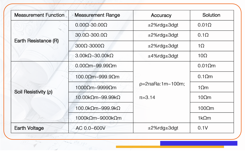
Figure 4: Measurement Specifications
| Parameter | Value |
|---|---|
| Earth Resistance Range | 0.00Ω - 30.00kΩ |
| Soil Resistivity Range | 0.00Ωm - 9000kΩm |
| Earth Voltage Range | AC 0V - 600V |
| Measurement Methods | 2-wire, 3-wire, 4-wire |
| Technology | FFT, AFC |
| Data Storage | 300 sets |
| Display | Large LCD with white backlight |
| Protection Rating | IP65 |
| Power Source | Rechargeable Lithium Ion Battery (included) |
| Package Dimensions | 14 x 13 x 12.19 inches |
| Weight | 12.95 Pounds |
| Operating Temperature | 10 Degrees Celsius and above |
| Certifications | CE, IEC 61010-1:2000-1 |
10. Warranty and Support
The SULMILE ETCR3100C Soil Resistivity and Earth Resistance Tester comes with a standard manufacturer's warranty. Please refer to the warranty card included in your package for specific terms and conditions, including warranty duration and coverage details.
For technical support, troubleshooting assistance, or warranty claims, please contact SULMILE customer service. Contact information can typically be found on the warranty card, the SULMILE official website, or through your point of purchase.