
1. Introduction
This manual provides detailed instructions for the installation, operation, and maintenance of your CAME BPT Video Door Intercom System, model 8K40CF-021. This system is designed to enhance security and convenience for single-family homes, bi-villas, townhouses, or properties with independent entrances. Please read this manual thoroughly before installation and use to ensure proper functioning and safety.
2. Product Overview
The CAME BPT 8K40CF-021 system comprises three main components:
- PLX V Hands-free Receiver: An indoor unit with a 5-inch LCD display for viewing visitors and communicating.
- LHS V/01 External Video Door Intercom: An outdoor unit with a camera and call button.
- VAS/101 Power Supply: Provides necessary power to the system.
The system utilizes an X1 Bus connection for simplified wiring.

Figure 2.1: Main components of the CAME BPT 8K40CF-021 Video Door Intercom System. Shown are the outdoor video door station, the indoor video monitor, and the power supply unit.

Figure 2.2: The PLX V indoor hands-free receiver with its 5-inch LCD display and soft-touch buttons.

Figure 2.3: The LHS V/01 external video door intercom unit, featuring a camera and call button.
3. Setup and Installation
Installation of the CAME BPT 8K40CF-021 system is designed to be straightforward. It is recommended that installation be performed by a qualified technician.
3.1. Components Check
Before beginning, ensure all components are present:
- 1 x PLX V Hands-free Receiver
- 1 x LHS V/01 External Video Door Intercom
- 1 x VAS/101 Power Supply
- Mounting hardware (screws, wall plugs)
3.2. Mounting the Outdoor Unit (LHS V/01)
- Choose a suitable location near your entrance, ensuring clear visibility of visitors and protection from direct heavy rain.
- Mark drilling points using the mounting template (if provided) or the unit itself.
- Drill holes and insert wall plugs.
- Connect the X1 Bus wiring to the terminals on the back of the LHS V/01 unit.
- Secure the unit to the wall using the provided screws.

Figure 3.1: Proper placement and interaction with the outdoor unit.

Figure 3.2: Detail of the outdoor unit, showing the camera lens and customizable nameplate area.
3.3. Mounting the Indoor Unit (PLX V)
- Select an indoor location, typically near the main entrance or in a central living area, where the display is easily visible.
- Mount the wall bracket (if applicable) and connect the X1 Bus wiring to the PLX V unit.
- Secure the PLX V unit to its bracket or directly to the wall.
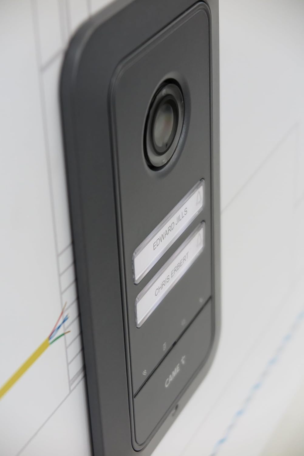
Figure 3.3: The indoor monitor installed on a wall, showing a user interacting with its touch buttons.
3.4. Power Supply Connection (VAS/101)
- Install the VAS/101 power supply in a secure, dry location, typically in an electrical panel or junction box.
- Connect the power supply to the main electrical circuit (ensure power is off before connecting).
- Connect the X1 Bus output from the power supply to both the outdoor and indoor units according to the wiring diagram (refer to the separate wiring diagram provided with your kit).
- Once all connections are secure, restore power to the system.

Figure 3.4: The VAS/101 power supply unit, essential for system operation.
4. Operating Instructions
The PLX V indoor unit features a 5-inch LCD display and soft-touch buttons for intuitive control.
4.1. Receiving a Call
- When a visitor presses the call button on the outdoor unit, the indoor unit will ring and display the visitor's image.
- Press the Answer button (typically represented by a phone icon) to establish two-way audio communication.
- To open the door/gate, press the Door Release button (typically represented by a key icon).
- To end the call, press the End Call button (often the same as the Answer button, or a distinct hang-up icon).
4.2. Monitoring the Entrance
You can view the outdoor area at any time without a visitor pressing the call button:
- Press the Monitor button (typically represented by an eye icon) on the indoor unit. The display will show the live feed from the outdoor camera.
- Press the Monitor button again to turn off the display.
4.3. Adjusting Settings
The PLX V unit allows for various adjustments:
- Ringtone: Use the dedicated button to adjust or exclude the ringtone volume.
- Brightness/Contrast: Access the menu (often via a 'Menu' or 'Settings' button) to adjust display brightness and contrast.
- Intercom Calls: If multiple indoor units are installed, use the auxiliary buttons for internal intercom communication.

Figure 4.1: Detailed view of the soft-touch control buttons on the indoor monitor, including call, monitor, and door release functions.
5. Maintenance
Regular maintenance ensures the longevity and optimal performance of your video door intercom system.
- Cleaning: Use a soft, damp cloth to clean the surfaces of both indoor and outdoor units. Avoid abrasive cleaners or solvents.
- Outdoor Unit Camera: Periodically clean the camera lens on the LHS V/01 unit to ensure clear image quality.
- Wiring: Periodically check all visible wiring for any signs of damage or loose connections.
- Software Updates: Check the CAME official website for any available firmware updates for your system.
Caution:
- Do not attempt to open or repair the units yourself. Refer to qualified service personnel.
- Ensure power is disconnected before performing any cleaning or inspection of electrical components.
6. Troubleshooting
If you encounter issues with your CAME BPT Video Door Intercom System, refer to the following common problems and solutions:
| Problem | Possible Cause | Solution |
|---|---|---|
| No image on indoor display. |
|
|
| No audio during calls. |
|
|
| Door release not working. |
|
|
| Outdoor unit not ringing indoor unit. |
|
|
7. Specifications
| Feature | Detail |
|---|---|
| Model | 8K40CF-021 |
| Brand | Came |
| Indoor Unit (PLX V) Display | 5-inch LCD |
| Outdoor Unit (LHS V/01) Camera | Wide eye optics, 98° horizontal, 72° vertical viewing angle |
| Outdoor Unit Protection Class | IK09 (impact resistant Zamak surface) |
| Connectivity | X1 Bus system, Wi-Fi (for potential smart features/app integration) |
| Power Supply | VAS/101, 18 V DC - 1000 mA |
| Max. Supported Devices | Up to 4 calls (expandable with button set) |
| Color | White Zamak (Indoor Unit), Grey (Outdoor Unit) |
| Item Weight | 1 Kilogram (total system) |
8. Warranty and Support
CAME products are known for their quality and reliability. For specific warranty information, please refer to the warranty card included with your product or visit the official CAME website. For technical assistance, troubleshooting beyond this manual, or service inquiries, please contact CAME customer support or your authorized dealer.
CAME Official Website: www.came.com
