1. Introduction
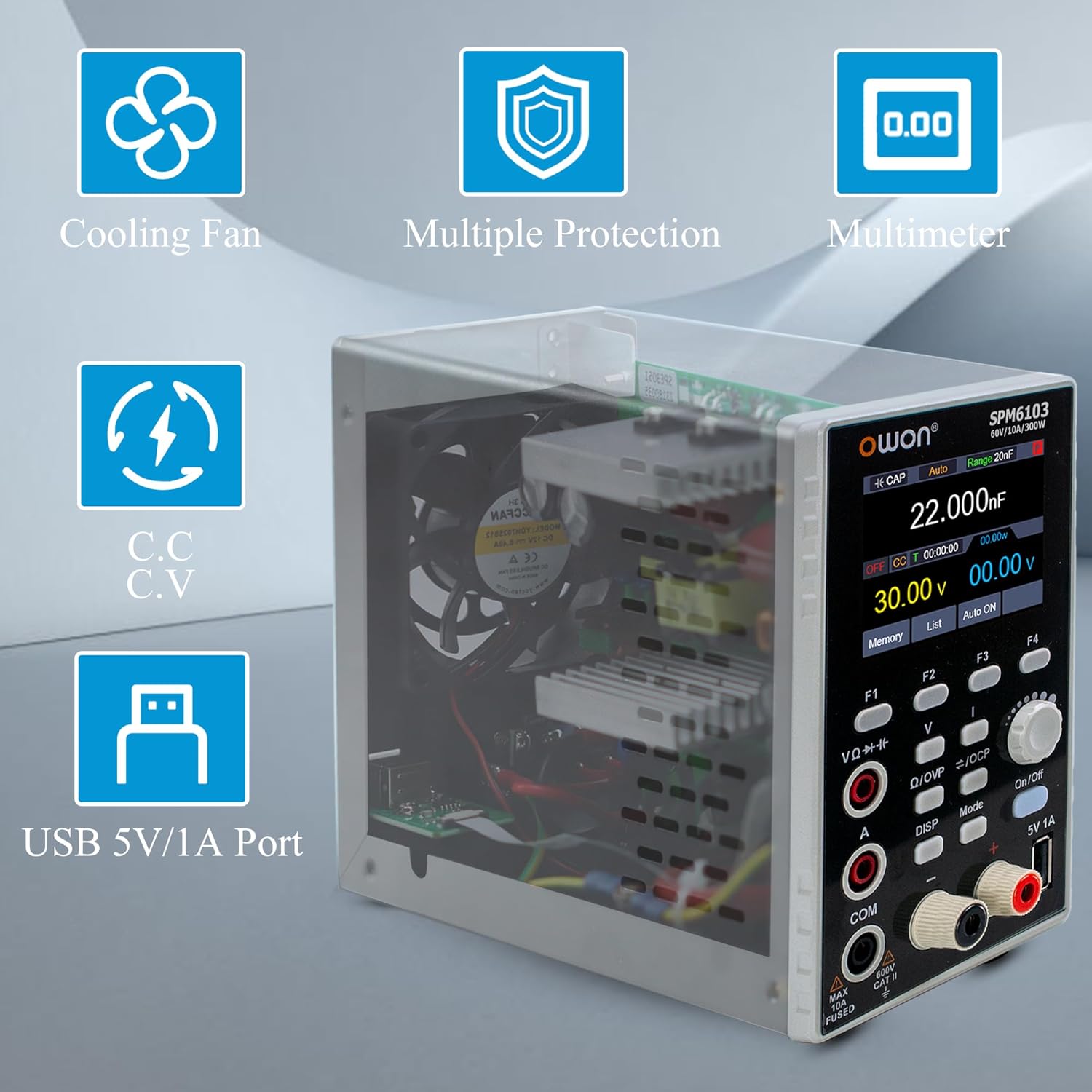
The OWON SPM6103 is a versatile 2-in-1 instrument combining a high-resolution DC power supply and a 4 1/2 digit multimeter. It offers an output power of 300W with a voltage range of 0-60V and a current range of 0-10A. Key features include a 2.8-inch LCD, 10mV/1mA power resolution, output voltage and current curve monitoring, and multiple protection mechanisms. The integrated multimeter supports measurements for voltage, current, capacitance, resistance, continuity, and diode testing.
2. Safety Information
Before operating the OWON SPM6103, please read and understand all safety instructions. Failure to follow these instructions may result in electric shock, fire, or damage to the device.
- Ensure the device is connected to a properly grounded AC power outlet.
- Do not operate the device in wet or damp conditions.
- Do not open the device casing; there are no user-serviceable parts inside except for the fuse. Refer servicing to qualified personnel.
- Verify correct voltage and current settings before connecting to a circuit to prevent damage to the device under test.
- Use only the specified fuse type and rating for replacement.
- Avoid touching live terminals during operation.
3. Product Overview
3.1 Front Panel
The front panel features the 2.8-inch LCD display, control buttons, an adjustment knob, output terminals, multimeter input jacks, and a 5V/1A USB host port.


3.2 Rear Panel
The rear panel includes the AC power input jack, power button, fuse holder, and a device USB port for PC connectivity.

4. Setup
4.1 Unpacking and Inspection
Carefully remove the SPM6103 from its packaging. Inspect the device for any signs of physical damage. Retain the packaging for future transport or storage.
4.2 Power Connection
- Ensure the power switch on the rear panel is in the OFF position.
- Connect the provided AC power cord to the AC power input jack on the rear panel (refer to Figure 3).
- Plug the other end of the power cord into a grounded AC power outlet (100-120V AC).
4.3 Connecting Test Leads
For power supply output, connect test leads to the red (+) and black (-) output terminals on the front panel. For multimeter measurements, connect probes to the VΩ-Hz, A, and COM input jacks as appropriate for the measurement type.
4.4 Initial Power-On
Press the power button on the rear panel to turn on the device. The 2.8-inch LCD will illuminate, displaying the startup sequence and then the default operating screen.
5. Operating Instructions
5.1 Power Supply Mode
- Setting Voltage and Current: Use the 'V' and 'I' buttons to select the voltage or current parameter. Rotate the adjustment knob to change the value. Press the knob to confirm or switch between coarse/fine adjustment.
- Output Control: Press the 'On/Off' button to enable or disable the power output. The display will indicate the output status.
- Curve Monitoring: The device can display output voltage and current curves. Use the 'DISP' button to cycle through display modes until the curve monitoring screen is shown.
- List Waveform Editing: The SPM6103 supports editing and outputting 10 groups of timing outputs. Press the 'List' button to access this function.
- Memory Shortcuts: Four groups of memory shortcut parameters are available for quick output settings. Use the 'Memory' button to save or recall these settings.

5.2 Multimeter Mode
The SPM6103 integrates a 4 1/2 digit multimeter with auto-ranging capabilities.
- Switching Modes: Press the 'Mode' button to switch between DC power supply and Multimeter modes.
- Measurements: Connect the multimeter probes to the appropriate input jacks (VΩ-Hz, A, COM). The device supports measuring voltage, current, capacitance, resistance, continuity, and diode (0-2V).

5.3 USB Host Port (5V/1A)
The front panel features a 5V/1A USB host port for charging small electronic devices or powering USB-compatible accessories.
6. Maintenance
6.1 Cleaning
To clean the device, disconnect it from all power sources and use a soft, dry cloth. Do not use abrasive cleaners or solvents. Ensure no liquids enter the device.
6.2 Fuse Replacement
The device is equipped with a user-replaceable fuse located on the rear panel (refer to Figure 3). If the device fails to power on, check the fuse. To replace:
- Disconnect the power cord from the AC outlet.
- Use a flat-head screwdriver to open the fuse holder.
- Remove the old fuse and replace it with a new fuse of the same type and rating (e.g., 10A, 250V).
- Close the fuse holder securely.
6.3 Cooling Fan
The SPM6103 includes an intelligent temperature-controlled fan for heat dissipation. The fan will activate automatically when the internal temperature rises. Ensure the rear panel's fan vents are not obstructed to allow for proper airflow.
7. Troubleshooting
- Device does not power on: Check the AC power cord connection and verify the fuse on the rear panel. Replace the fuse if blown.
- No output from power supply: Ensure the 'On/Off' button has been pressed to enable output. Check that voltage and current limits are set appropriately.
- Multimeter readings are inaccurate: Verify probe connections are secure and correctly inserted for the desired measurement type. Ensure the 'Mode' is set to Multimeter.
- 5V USB host port not charging: Some users have reported issues with the 5V USB connection. Ensure the connected device is compatible and try a different USB cable. If the issue persists, contact support.
- PC software display in incorrect language: If using the PC software, locate the language settings within the application. For initial setup, a button in the lower-left corner of the software interface may switch the display to English.
- Fan noise: The intelligent temperature-controlled fan will operate when the device reaches a certain temperature. This is normal. If the fan runs excessively or makes unusual noises, ensure vents are clear.
8. Specifications
| Feature | Specification |
|---|---|
| Model | SPM6103 |
| Output Power | 300W |
| Output Voltage | 0-60V |
| Output Current | 0-10A |
| Power Resolution | 10mV / 1mA |
| Multimeter Digits | 4 1/2 Digits |
| Multimeter Functions | Voltage, Current, Capacitance, Resistance, Continuity, Diode (0-2V) |
| USB Host Port | 5V / 1A |
| Display | 2.8 inch LCD |
| Protections | Over Voltage Protection (OVP), Over Current Protection (OCP), Over Heating Protection, Over Circuit Protection, Over Load Protection |
| Timing Output Groups | 10 groups editable |
| Memory Parameters | 4 groups shortcut parameters |
| Dimensions | 22.58 x 8.2 x 14.2 cm |
| Weight | 1.5 kg |
9. Warranty and Support
For warranty information, technical support, or service inquiries, please contact OWON customer service or refer to the official OWON website. Keep your purchase receipt for warranty claims.


