
1. Introduction
This manual provides detailed instructions for the installation, operation, and maintenance of the DEWIN 220V 1.5KW Single-Phase Input Three-Phase Output VFD Frequency Converter. Please read this manual thoroughly before use to ensure safe and efficient operation of the device. This frequency converter is designed to control the speed of three-phase AC motors by varying the frequency and voltage of the power supplied to the motor.
2. Safety Information
WARNING: Read the user manual before operation. Risk of electrical shock. Wait 10 minutes after removing power before servicing.
- Ensure the power supply matches the converter's specifications (Single Phase 220V).
- All wiring must be performed by qualified personnel in accordance with local electrical codes.
- Do not touch internal components immediately after disconnecting power, as residual voltage may be present.
- Ensure proper grounding to prevent electrical hazards.
- Do not operate the converter in environments with excessive dust, moisture, or corrosive gases.
3. Product Overview and Features
The DEWIN VFD Frequency Converter offers precise motor speed control with several protective and efficiency-enhancing features.

Figure 3.1: General view of the DEWIN VFD Frequency Converter, highlighting motor protection, energy saving, frequency control, and strong security features.
3.1 Key Features
- Motor Protection: Integrated features to safeguard connected motors.
- Energy Saving: Optimizes motor operation for reduced power consumption.
- Frequency Control: Allows precise adjustment of output frequency for variable speed applications.
- Strong Security: Designed with robust safety measures.
- Removable Control Panel: Facilitates easier wiring and maintenance.
- Efficient Heat Dissipation: Equipped with a radiator for stable long-term operation.
3.2 Operation Interface
The control panel provides a clear display and intuitive buttons for operation.
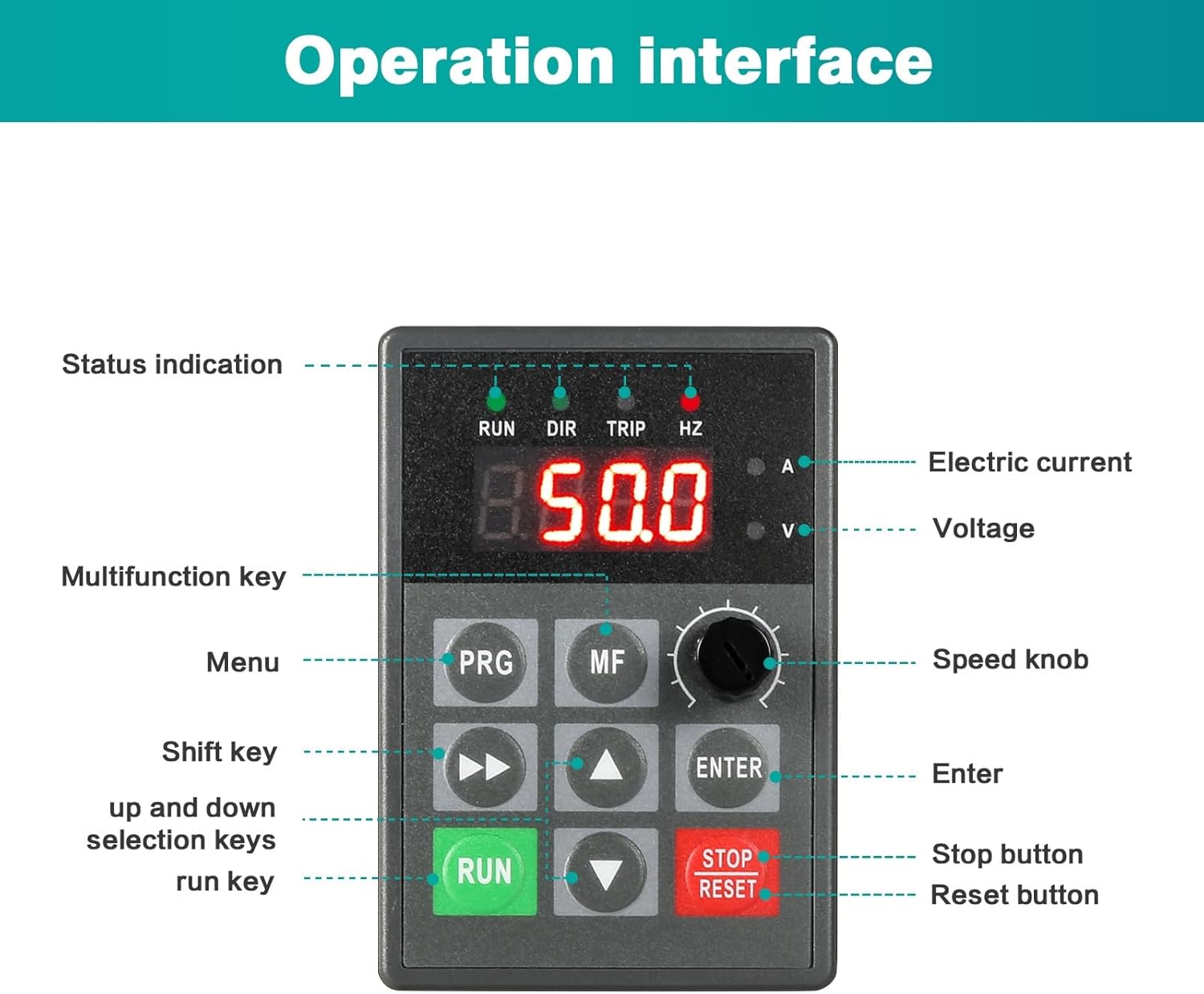
Figure 3.2: Detailed view of the operation interface, showing status indicators, display, and control buttons.
- Status Indication: RUN (running), DIR (direction), TRIP (fault), HZ (frequency).
- Display: Shows frequency, voltage, and current values.
- PRG (Menu) Key: Enters/exits parameter setting mode.
- MF (Multifunction) Key: Used for various functions depending on the mode.
- Speed Knob: Rotary knob for stepless frequency adjustment (0-50Hz).
- Shift Key (>>): Moves cursor or shifts digits during parameter setting.
- Up/Down Keys (▲ / ▼): Adjusts parameter values or navigates menus.
- ENTER Key: Confirms selections or parameter changes.
- RUN Key: Starts motor operation.
- STOP/RESET Key: Stops motor operation or resets fault conditions.
4. Setup and Installation
Proper installation is crucial for the safe and reliable operation of the frequency converter.
4.1 Mounting
- The converter is designed for wall-mounted or cabinet installation.
- Ensure adequate ventilation around the unit to facilitate heat dissipation. Maintain sufficient clearance from other equipment.
- Mount the unit vertically to optimize cooling airflow.

Figure 4.1: Physical dimensions of the frequency converter (23 x 17 x 16 cm).
4.2 Wiring
The control panel can be removed to access wiring terminals easily.

Figure 4.2: The removable control panel simplifies access to wiring terminals.
- Connect the single-phase 220V input power to the designated terminals.
- Connect the three-phase motor to the output terminals (U, V, W).
- Ensure all connections are secure and properly insulated.
- Refer to the detailed wiring diagram in the complete product manual for specific terminal assignments.
5. Operating Instructions
Follow these steps for basic operation of the frequency converter.
5.1 Power On
- After ensuring all wiring is correct and secure, apply power to the converter.
- The display will light up, showing the current frequency or other default parameters.
5.2 Adjusting Speed/Frequency
The speed knob allows for stepless adjustment of the output frequency.

Figure 5.1: The speed knob provides continuous frequency adjustment.
- Rotate the Speed Knob clockwise to increase the output frequency and motor speed.
- Rotate the Speed Knob counter-clockwise to decrease the output frequency and motor speed.
- The display will show the current output frequency (Hz).
5.3 Starting and Stopping the Motor
- To start the motor, press the green RUN button. The RUN indicator will illuminate.
- To stop the motor, press the red STOP/RESET button. The RUN indicator will turn off.
5.4 Parameter Settings
Advanced settings and parameters can be accessed via the PRG (Menu) and MF (Multifunction) keys. Refer to the comprehensive manual for detailed parameter descriptions and adjustment procedures.
6. Maintenance
Regular maintenance ensures the longevity and optimal performance of your frequency converter.
- Power Disconnection: Always disconnect power and wait at least 10 minutes after removing power before performing any maintenance or servicing to avoid electrical shock.
- Cleaning: Keep the unit clean and free from dust and debris. Use a soft, dry cloth for cleaning. Do not use liquid cleaners.
- Ventilation: Ensure the radiator fins are clear of obstructions to maintain effective heat dissipation.
- Connections: Periodically check all electrical connections for tightness and signs of corrosion.

Figure 6.1: The integrated radiator ensures efficient heat dissipation for stable operation.
7. Troubleshooting
This section provides general guidance for common issues. For specific fault codes and detailed troubleshooting steps, please refer to the complete product manual.
- No Power/Display Off: Check input power connections and circuit breaker.
- Motor Not Running: Verify RUN command, check motor wiring, ensure frequency setting is not zero.
- Overcurrent/Overload Trip: Check motor load, ensure motor power matches converter rating, inspect for mechanical issues in the motor or driven equipment.
- Overvoltage/Undervoltage Trip: Check input voltage stability.
- Overheat Trip: Ensure proper ventilation, clean radiator fins, reduce ambient temperature if necessary.
8. Specifications
Technical specifications for the DEWIN 220V 1.5KW Single-Phase Input Three-Phase Output VFD Frequency Converter.

Figure 8.1: Overview of the product specifications.
| Specification | Value |
|---|---|
| Model | JLS-E-2S-1.5G |
| Material | Process flame retardant ABS plastic |
| Color | White |
| Rated Input Voltage | Single Phase 220V |
| Rated Output Voltage | Three-phase 220V |
| Rated Power | 1.5KW |
| Output Current | 7A |
| Factory Frequency | 50Hz |
| Output Frequency Range | 0-999Hz |
| Installation Method | Wall-mounted, cabinet |
| Nature of DC Power Supply | Voltage Type |
| Control Mode | V/F closed loop |
| Output Voltage Regulation Method | PAM control |
| Product Dimensions | 23 x 17 x 16 cm |
| Product Weight | 1.22 kg |
9. Applications
The DEWIN VFD Frequency Converter is suitable for a wide range of industrial applications requiring variable speed control for three-phase motors.

Figure 9.1: Common applications include motors, water pumps, and fans.
- Motors: General purpose motor speed control.
- Water Pumps: For flow and pressure regulation.
- Fans: For airflow control in ventilation systems.
- Blenders: For industrial mixing processes.
- Air Compressors: For optimizing compressor performance.
- Conveyor Belts: For precise speed control in material handling.
10. Video Demonstrations
Watch the official product video for a visual overview of the DEWIN VFD Frequency Converter.
Video 10.1: A brief demonstration of the DEWIN VFD Frequency Converter, showcasing its physical appearance and design.