1. Introduction
This manual provides comprehensive instructions for the DIYmall ESP32 Expansion Board. This board is designed to simplify the connection and power management for the DIYmall ESP32 Development Board, making it easier to integrate various sensors and modules into your projects. Please read this manual carefully before use to ensure proper setup and operation.
2. Features
- Designed exclusively for DIYmall ESP32 Development Boards.
- Breaks out all pins of the DIYmall ESP32 Development Board to standard 2.54mm pin headers for easy access.
- Includes two additional rows of 2.54mm pin headers, providing a stable 3.3V DC power supply for external sensors and modules.
- Supports external power input from DC 6.5V to 30V via a dedicated black DC jack.
- Integrated DIP switch for convenient power control (ON/OFF).
3. Package Contents
- 1 x DIYmall ESP32 Expansion Board
4. Setup
4.1. Connecting the ESP32 Development Board
Align the pins of your DIYmall ESP32 Development Board with the corresponding headers on the ESP32 Expansion Board. Gently press the development board into place until it is securely seated. Ensure all pins are correctly aligned to prevent damage.
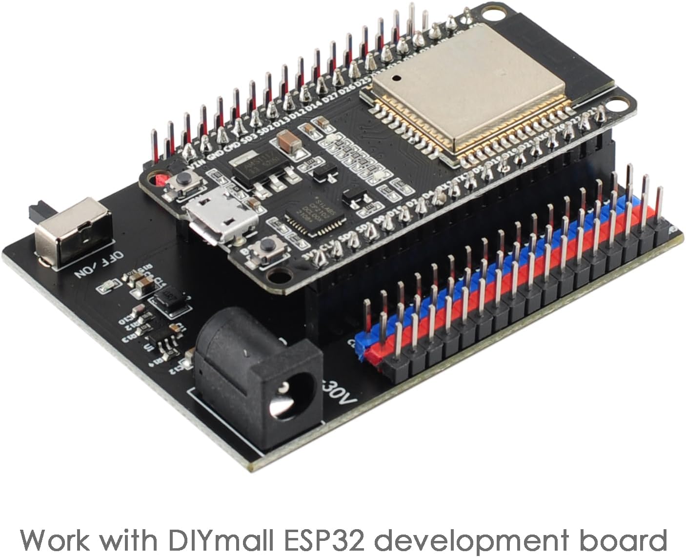
Image: A DIYmall ESP32 Development Board securely mounted onto the ESP32 Expansion Board, demonstrating the correct connection method.
Video: This video demonstrates the physical connection process of the ESP32 Development Board to the Expansion Board, showing how to properly align and insert the development board.
4.2. Powering the Expansion Board
The expansion board can be powered via the black DC jack, which accepts a voltage range of 6.5V to 30V DC. Ensure the power supply polarity is correct before connecting. Use the 'OFF/ON' DIP switch located on the board to control the power supply to the entire setup.

Image: A detailed diagram of the ESP32 Expansion Board highlighting the external power interface (DC 6.5-30V) and the power control switch (OFF/ON).
5. Operating Instructions
5.1. Pin Breakout
The expansion board provides convenient access to all GPIO pins of the connected ESP32 Development Board through clearly labeled 2.54mm pin headers. This allows for easy prototyping and connection of various components without needing a breadboard for the main ESP32 module. Refer to the pinout diagram printed on the board for specific pin functions and numbering.
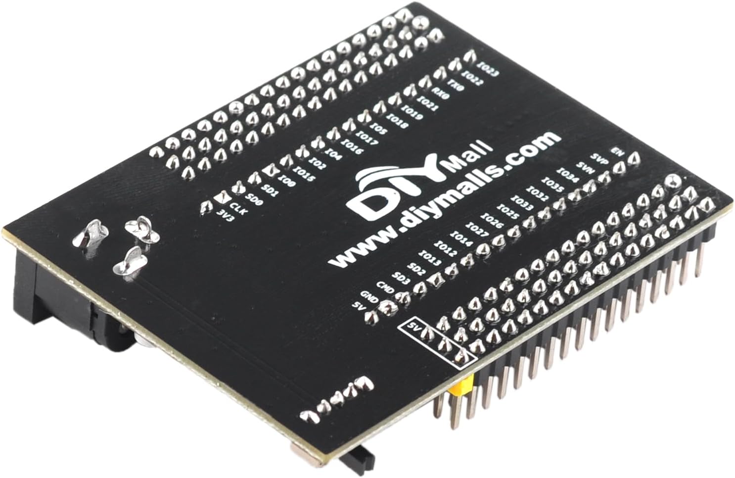
Image: An overhead view of the ESP32 Expansion Board, clearly showing the labels for each broken-out pin, including GPIO numbers, power, and ground connections.
5.2. External Sensor Power
The board features dedicated 3.3V and GND pins on the additional pin header rows for powering external sensors and modules. These pins provide a stable 3.3V DC output, suitable for most common microcontroller peripherals. Always verify the voltage requirements of your external components before connecting them to these pins.
6. Specifications
| Feature | Detail |
|---|---|
| Brand | DIYmall |
| Series | ESP32 Expansion Board |
| Item Weight | 0.96 ounces |
| Package Dimensions | 3 x 3 x 1 inches |
| Power Input | DC 6.5V - 30V |
| Output Voltage for Sensors | DC 3.3V |
| Connectivity Technology (via ESP32) | Bluetooth, Wi-Fi |
| Included Components | ESP32-WROOM-32 Expansion Board |

Image: Diagram illustrating the physical dimensions of the ESP32 Expansion Board, showing measurements in both millimeters and inches.
7. Maintenance
7.1. General Care
To ensure the longevity and proper functioning of your ESP32 Expansion Board, keep it in a dry, dust-free environment. Avoid exposure to extreme temperatures, high humidity, or corrosive substances. Do not apply excessive force when connecting or disconnecting components, as this may damage the pins or the board itself.
7.2. Cleaning
If cleaning is necessary, gently wipe the board with a soft, dry, lint-free cloth. Do not use liquid cleaners, solvents, or abrasive materials, as these can damage the electronic components or the board's finish.
8. Troubleshooting
8.1. Power Issues
- Board does not power on: Ensure the DC power supply is within the specified 6.5V-30V range and is correctly connected to the DC jack. Verify that the power control switch is in the 'ON' position.
- Unstable power to external sensors: Check the connections to the 3.3V and GND pins. Ensure the total current draw of your external sensors does not exceed the board's capabilities.
8.2. Pin Compatibility
- ESP32 Development Board does not fit: This expansion board is designed specifically for DIYmall ESP32 Development Boards, particularly those with a 36-pin configuration (like the ESP32-WROOM-32). Ensure your ESP32 development board is compatible with this pin layout. Boards with different pin counts (e.g., 30-pin) will not fit correctly.
9. Warranty and Support
9.1. Warranty Information
For specific warranty details regarding your DIYmall ESP32 Expansion Board, please refer to the product packaging or the official DIYmall website. Warranty terms may vary based on region and purchase date.
9.2. Customer Support
Should you require technical assistance, have questions about product functionality, or need further support, please visit the official DIYmall store on Amazon or their dedicated support channels. Providing your product model and purchase details will help expedite support requests.


