1. Safety Precautions
- Do not disassemble or modify this product. Internal components are high-voltage.
- Keep the product dry. Do not handle with wet hands or immerse in water.
- Do not use in the presence of flammable gases or liquids.
- Ensure the power supply voltage matches the product's requirements.
- Unplug the power cord before cleaning or when not in use for extended periods.
- Avoid direct eye exposure to the flash.
2. What's in the Box
Verify that all components are present upon unboxing.

Image: The Godox DP1000III-V flash head, a mains power cable, and a protective lamp cover are included in the package.
- DP1000III-V Flash Head (x1)
- Power Cord (x1)
- Lamp Cover (x1)
- Note: Stand and Wireless Trigger are typically sold separately or as part of a kit.
3. Setup
3.1 Mounting the Flash Head
Attach the DP1000III-V flash head to a compatible light stand using the integrated mounting bracket. Secure it firmly to prevent accidental falls.
3.2 Connecting Power
Insert the provided power cord into the electric socket on the rear of the flash head. Connect the other end to a suitable AC power outlet.
3.3 Attaching Accessories (Bowens Mount)
The DP1000III-V features a Bowens mount, allowing for a wide range of light modifiers. To attach an accessory:
- Align the accessory's mount with the Bowens mount on the flash head.
- Twist the accessory clockwise until it clicks into place, ensuring it is securely locked.
- To remove, press the release button on the flash head and twist the accessory counter-clockwise.

Image: The flash head is shown with a standard reflector being attached, demonstrating the Bowens mount compatibility with various studio accessories.
4. Operating Instructions
4.1 Control Panel Overview
The rear panel of the DP1000III-V provides access to all operational controls and the LCD display.

Image: The control panel features an LCD display, selector dial with SET button, buttons for Channels/Groups, Wireless, S1/S2 switching, Synchronized line jacks, Wireless Control Socket, Modeling light mode, C.Fn User-defined button, Beep Button, Test flash button, Power switch, and Electric socket.
- LCD Display: Shows current settings such as flash output, channel, group, and modeling lamp status.
- Selector Dial + SET Button: Rotate to adjust values, press SET to confirm.
- CH/GR Button: Selects channels and groups for wireless control.
- Wireless Button: Activates/deactivates the 2.4G Wireless X System.
- S1/S2 Switching: Enables optical slave modes.
- Modeling Light Button: Controls the 30W modeling lamp.
- C.Fn Button: Accesses custom functions.
- Beep Button: Toggles the audible flash ready indicator.
- Test Flash Button: Fires a test flash.
- Power Switch: Turns the unit on or off.
4.2 Flash Output Adjustment
The flash output can be adjusted from 1/64 to 1/1 in 61 precise steps. Rotate the selector dial to increase or decrease the power. The current setting is displayed on the LCD.
4.3 Modeling Lamp Operation
The DP1000III-V features a 30W LED modeling lamp. Press the Modeling Light button to cycle through modes (e.g., ON, OFF, Proportional). The brightness can be adjusted via the selector dial when the lamp is active.

Image: The 30W LED modeling light provides adjustable brightness for continuous illumination.
4.4 2.4G Wireless X System
The integrated Godox 2.4G Wireless X System allows for remote control of the flash. Use a compatible Godox X1, X2, XPro, or XT16 flash trigger (sold separately) to control flash power, modeling lamp, and trigger the flash wirelessly.
- Channels and Groups: Set the flash and trigger to the same channel and group for communication.
- Wireless ID (01-99): For enhanced anti-interference, set a unique Wireless ID on both the flash and trigger.
- Range: The wireless system operates effectively within a 50-meter range.
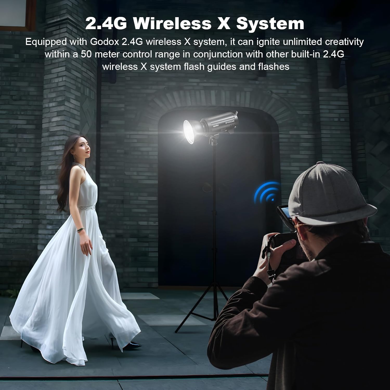
Image: The 2.4G Wireless X System enables remote control of the flash, offering creative flexibility.
4.5 Anti-Preflash Function
This function enables synchronization with cameras that emit a pre-flash for exposure metering. Activate this feature in the custom function settings if your camera uses a pre-flash system.
5. Maintenance
5.1 Cleaning
Regularly clean the flash unit with a soft, dry cloth. For stubborn dirt, use a slightly damp cloth and then dry thoroughly. Do not use solvents or abrasive cleaners.
5.2 Storage
When not in use, store the flash in a cool, dry place, away from direct sunlight and excessive humidity. Ensure the lamp cover is in place to protect the flash tube and modeling lamp.
5.3 Flash Tube and Modeling Lamp Replacement
The flash tube and modeling lamp are user-replaceable components. Refer to the Godox website or authorized service centers for replacement parts and detailed instructions if replacement is necessary.
6. Troubleshooting
- Flash not firing:
- Check power connection and ensure the unit is turned on.
- Verify the flash is fully recycled (beep sound or ready indicator).
- Ensure the trigger and flash are on the same channel and group for wireless operation.
- Check camera sync settings and cable connection for wired triggering.
- Inconsistent flash output:
- Ensure stable power supply.
- Check for overheating; allow the unit to cool if used continuously at high power.
- Wireless trigger not connecting:
- Confirm both devices are powered on and within range.
- Match channels, groups, and Wireless ID settings.
- Check battery levels in the wireless trigger.
7. Specifications
| Model | DP1000III-V |
| Max Power | 1000Ws |
| Guide Number (GN) | 140 (ISO 100, with standard reflector) |
| Color Temperature | 5600K ± 200K |
| Flash Duration | 1/2000s - 1/800s |
| Recycle Time | Approx. 1 second (at full power) |
| Flash Output Control | 61 steps (1/64 to 1/1) |
| Modeling Lamp | 30W LED, adjustable brightness |
| Wireless Function | 2.4G Wireless X System (Channels: 32, Groups: 16, ID: 01-99) |
| Sync Mode | Sync cord, Test button, Slave triggering, Wireless control port |
| Sync Speed | Up to 1/250s |
| Bowens Mount | Yes |
| Dimensions (L x W x H) | 4.9 x 16.1 x 8.5 inches (12.4 x 40.9 x 21.6 cm) |
| Weight | 10.21 lbs (4.63 kg) |
8. Warranty and Support
For detailed warranty information, please refer to the official Godox website or the warranty card included with your product. For technical support, service, or inquiries about replacement parts, please contact Godox customer service or your authorized dealer.
Official Godox Website: www.godox.com