1. Introduction
This manual provides essential information for the proper installation, operation, and maintenance of your eletechsup DC 12V 24V Multifunction ESP32 Expansion Board (ES32A08). This board is designed to extend the capabilities of a 38-pin ESP32 development board, offering a wide range of digital and analog I/O, relay outputs, and communication interfaces for various DIY and industrial applications.
2. Product Features
- Working Voltage: DC 12V-24V.
- Current Consumption: Standby current (Digital tube OFF) 15MA, Standby current (Digital tube ON) 50MA. Current increases with active relays (e.g., 1 relay open 76MA, 8 relays open 292MA).
- On-board Resources:
- 1x RS485 Interface
- 8x Opto-isolated Digital Inputs (low level trigger, NPN type)
- 4x 0/4-20MA Current Inputs
- 4x 0-5V/10V Voltage Inputs
- 4x User Buttons
- 1x 4-bit Digital Tube Display
- 1x 38-pin ESP32 Slot
- 8x Relay Outputs
- Dimensions (ES32A08 Only Board): 180mm x 72mm x 20mm.
- Weight (ES32A08 Only Board): 189g.
The board supports two widths of 38-pin ESP32 boards: 22.5mm and 25.4mm pin header spacing.
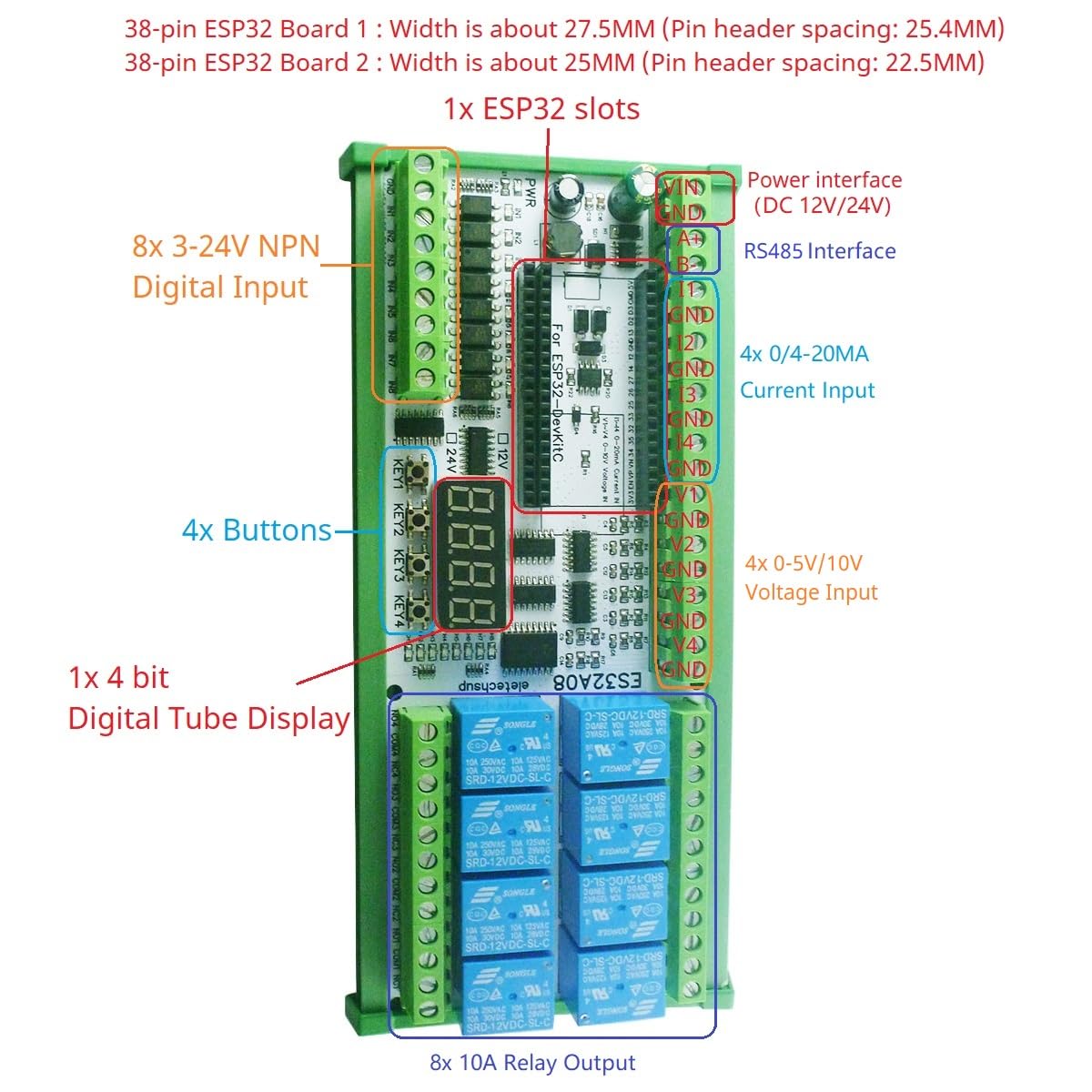
Image: Overview of the ES32A08 board, highlighting the ESP32 slot, various inputs, outputs, and display. It also shows compatibility with different ESP32 board widths.
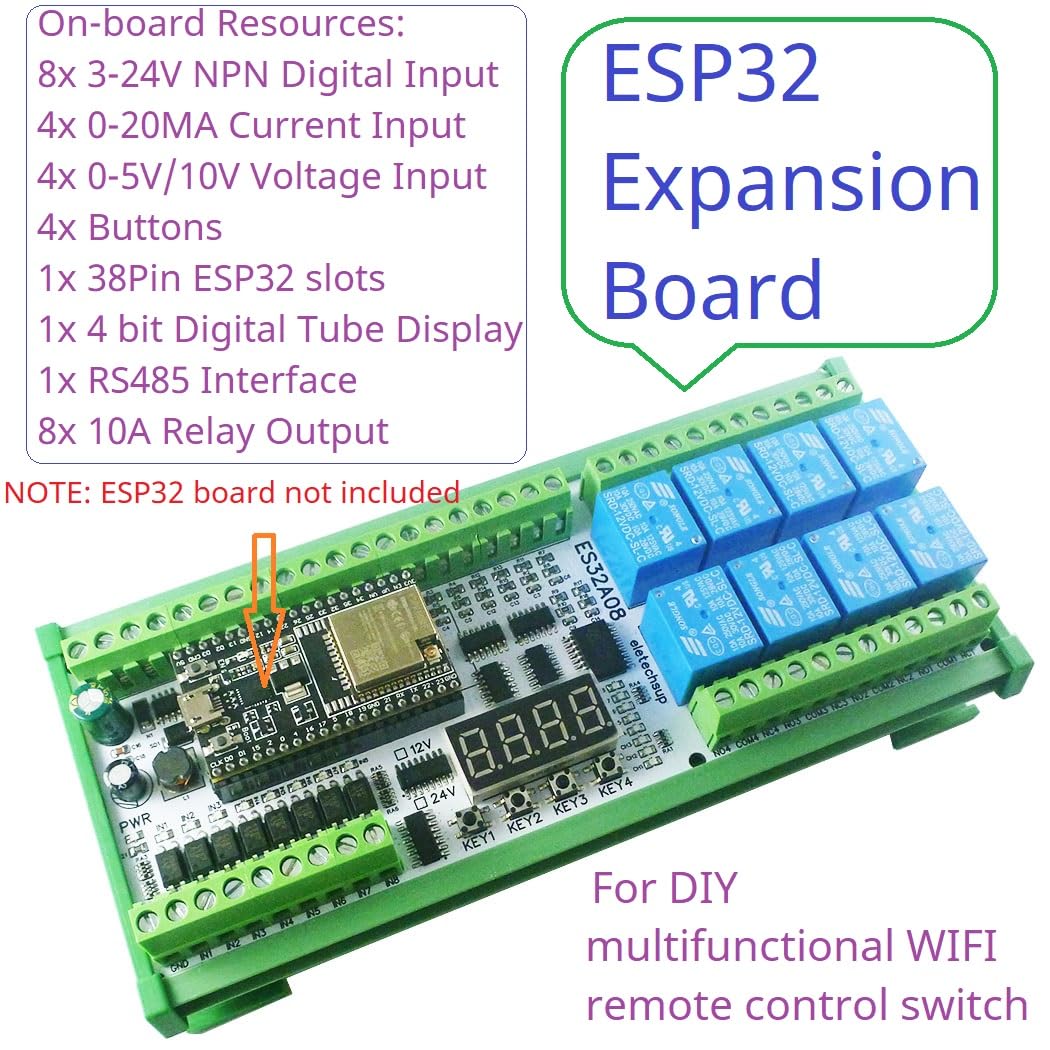
Image: The ES32A08 board with an ESP32 module installed, illustrating the on-board resources such as digital inputs, current/voltage inputs, buttons, digital display, RS485 interface, and relay outputs.
3. Setup
3.1. Required Components
The ES32A08 expansion board cannot operate independently. It requires a 38-pin ESP32 development board to function. Ensure you have a compatible 38-pin ESP32 board before proceeding with setup.
3.2. Board Installation
- Carefully align your 38-pin ESP32 board with the designated ESP32 slot on the ES32A08 expansion board.
- Gently press the ESP32 board into the slot, ensuring all pins are correctly seated.
- Connect a DC 12V-24V power supply to the power interface terminals (labeled PWR) on the ES32A08 board. Observe correct polarity.

Image: The ES32A08 board illustrating the insertion of a 38-pin ESP32 development board into its socket, with measurements for pin header spacing.
4. Operating Instructions
4.1. Programming the ESP32
This expansion board functions under the control of the ESP32. You will need to write custom ESP32 code to utilize its features. The manufacturer provides basic VSCode code examples for hardware testing. For advanced functionalities, custom code development is required.
4.2. Input/Output Connections
Refer to the board's silkscreen labels and the provided diagrams for connecting external devices to the various inputs and outputs:
- RS485 Interface: Connect A+ and B- terminals for RS485 communication.
- Digital Inputs (IN1-IN8): Connect NPN type low-level trigger signals.
- Current Inputs (I1-I4): Connect 0/4-20MA current sources.
- Voltage Inputs (V1-V4): Connect 0-5V or 0-10V voltage sources. Note that V3 and V4 voltage measurement channels cannot be used simultaneously with WiFi.
- Relay Outputs (NC/NO/COM): Connect loads to the normally open (NO), normally closed (NC), and common (COM) terminals of the 8 relays.

Image: Detailed wiring diagram for the ES32A08 board, showing connections for DC power, RS485, digital inputs, current inputs, voltage inputs, and relay outputs to external loads.
4.3. Application Examples
With appropriate ESP32 programming, this board can be used for various applications, including:
- WiFi remote control switches.
- WiFi current and voltage data collection.
- Home automation and smart home DIY projects.
- RS485 master-slave device control (e.g., PLC, MCU).
- Motor forward and reverse control.
- Timing ON/OFF functions.
- Various delay functions: power-up delay, trigger delay, infinite loop delay, finite cyclic delays.
- Power sequencer.
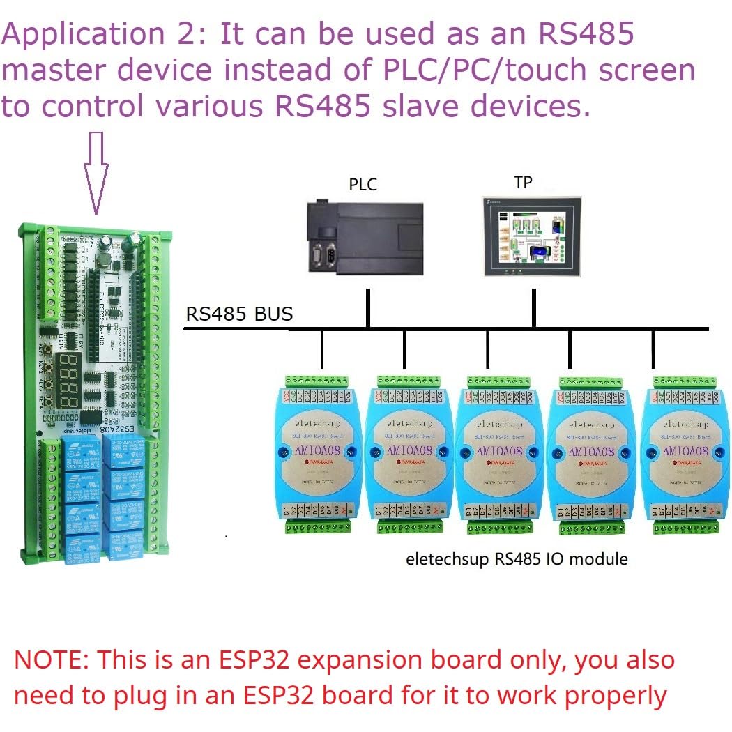
Image: An application example demonstrating the ES32A08 board acting as an RS485 master device, controlling multiple RS485 slave modules, replacing traditional PLC/PC/touch screen setups.
5. Maintenance
To ensure the longevity and reliable operation of your expansion board:
- Keep the board clean and free from dust and moisture.
- Avoid exposing the board to extreme temperatures or direct sunlight.
- Ensure proper ventilation if enclosed in a case.
- Regularly check all connections for secure fit.
- Disconnect power before making any wiring changes or performing maintenance.
6. Troubleshooting
- Board not powering on: Verify that the DC 12V-24V power supply is correctly connected and providing the specified voltage. Check for correct polarity.
- ESP32 not recognized or functioning: Ensure the 38-pin ESP32 board is properly seated in its slot. Confirm that the ESP32 board itself is functional.
- No information on I/O pin connections: The board's silkscreen provides labels for I/O. For detailed pin mapping to the ESP32, refer to the manufacturer's provided code examples or contact the seller for specific documentation.
- Analog input accuracy issues: The accuracy of analog quantity acquisition is determined by the ESP32 board. It is recommended to collect multiple readings and average them for improved accuracy.
- Relays not activating: Check your ESP32 code to ensure the relay control pins are correctly configured and being driven. Verify the power supply is sufficient for the relays.
7. Specifications
| Specification | Value |
|---|---|
| Working Voltage | DC 12V-24V |
| Current Rating | 0.29 Amps (per relay, typical) |
| Wattage | 7 watts |
| Coil Voltage | 12 Volts (DC) |
| Minimum Switching Voltage | 12 Volts (DC) |
| Maximum Switching Voltage | 24 Volts |
| Connector Type | Through Hole |
| Contact Material | Silver Alloy |
| Contact Type | Normally Open |
| Mounting Type | PCB Mount |
| Item Weight | 0.06 ounces (board only) |
8. Warranty and Support
Specific warranty information for this product is not provided in the available documentation. For any technical support, detailed pinout diagrams, or code examples beyond the basic hardware testing code, please contact the eletechsup seller directly through your purchase platform. They can provide further assistance and resources for your specific application needs.