1. Introduction
This manual provides essential instructions for the proper installation, operation, and maintenance of your BOATCON Marine 703 Remote Control Box. Please read this manual thoroughly before using the product to ensure safe and efficient operation. Keep this manual in a safe place for future reference.
2. Safety Information
Always prioritize safety when installing and operating marine equipment. Failure to follow these instructions could result in injury or damage to the product or vessel.
- Ensure the engine is turned off and the battery is disconnected before performing any installation or maintenance.
- Always wear appropriate personal protective equipment (PPE) during installation.
- Verify all connections are secure and correctly wired according to the wiring diagram.
- Test all functions in a safe environment before operating the vessel at speed.
- The emergency stop switch lanyard must always be attached to the operator during engine use.
3. Package Contents
Verify that all items listed below are present in your package:
- 1 × Control Box
- 1 × Flameout Rope (Emergency Stop Lanyard)
- 2 × Keys
- 1 × Mounting Bolts and Spacer Kit
- 1 × Installation Instruction Manual (this document)
- 1 × 10-Pin 16.5FT (5m) Harness Cable
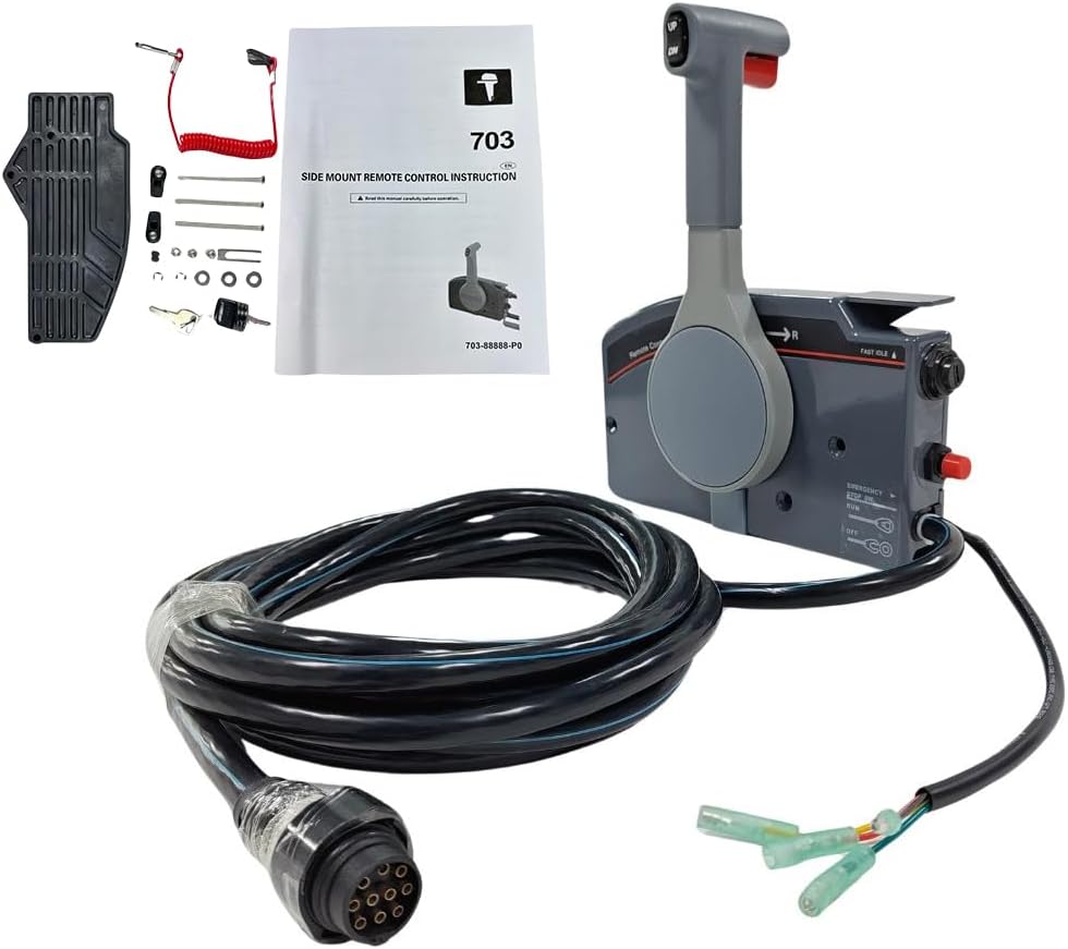
Figure 3.1: Contents of the BOATCON Marine 703 Remote Control Box package. Includes the control box, 10-pin harness, emergency stop lanyard, keys, and mounting hardware.
4. Product Overview
The BOATCON Marine 703 Remote Control Box is a side-mount unit designed for Yamaha Outboard Engines, featuring a 10-pin connector and a 16.5FT (5m) harness. It provides comprehensive control over your engine's functions.

Figure 4.1: Front view of the control box with key components labeled.
- Trim and Tilt Switches: Located on the handle for adjusting engine trim and tilt.
- Remote Control Lever: Controls gear shift (Forward, Neutral, Reverse) and throttle.
- Emergency Stop Switch: For immediate engine shutdown in emergencies. Requires lanyard attachment.
- Quick Idle Lever: Allows for engine warm-up without engaging the propeller.
- Key Switch: For starting and stopping the engine.
- Throttle Friction Adjuster: Adjusts the tension of the throttle lever.
- 10-Pin Harness Connector: Connects the control box to the engine's wiring harness.
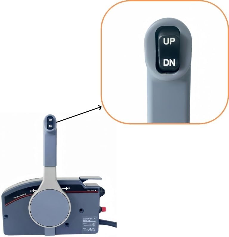
Figure 4.2: Detail of the UP and DN buttons for trim and tilt adjustment.

Figure 4.3: Detail of the engine key switch.

Figure 4.4: Detail of the emergency stop switch with its red cap and the lanyard attachment.
5. Installation and Setup
This control box is designed for right-hand surface side mounting. It can be installed on either the left or right side of the vessel, depending on the specific installation manual provided with your engine.
5.1 Mounting the Control Box
- Select a suitable mounting location on the side of your vessel, ensuring clear access to the control lever and switches.
- Use the provided mounting template (if available, otherwise measure carefully) to mark drilling points for the mounting bolts.
- Drill pilot holes as required.
- Secure the control box to the mounting surface using the supplied mounting bolts and spacers. Ensure a tight and stable fit.

Figure 5.1: Side view illustrating the mounting plate for surface installation.
5.2 Electrical Connections
The control box comes with a 10-pin harness. This harness connects the control box to your Yamaha Outboard Engine's electrical system. Ensure the engine is off and the battery is disconnected before making connections.
- Locate the corresponding 10-pin connector on your Yamaha Outboard Engine's wiring harness.
- Carefully align the pins and securely connect the control box harness to the engine harness.
- Route the cable safely, avoiding sharp edges or areas where it could be pinched or damaged. Use cable ties to secure the harness.
- Connect the emergency stop switch wires and other auxiliary wires (if applicable) as per your engine's wiring diagram.

Figure 5.2: The 10-pin connector for the main engine harness.
5.3 Control Cable Connection
This control box is suitable for 3300/33c universal control cables. These cables connect the control box to the engine's throttle and gear shift mechanisms.
- Attach the throttle and shift cables to the appropriate connection points on the control box and the engine.
- Ensure the cables are routed smoothly without sharp bends or kinks that could impede movement.
- Adjust the cable tension as needed to ensure smooth and responsive operation of the throttle and gear shift.

Figure 5.3: Example of control cables connected to the control box.
6. Operation
Familiarize yourself with the control box functions before operating your vessel.
6.1 Starting the Engine
- Ensure the emergency stop lanyard is properly attached to the emergency stop switch and to the operator.
- Insert the key into the key switch and turn it to the "ON" position.
- Place the remote control lever in the "NEUTRAL" position.
- Turn the key to the "START" position. Release the key once the engine starts; it will return to "ON".
6.2 Shifting Gears and Throttle Control
The remote control lever manages both gear selection and throttle.
- Neutral: The lever is in the vertical center position.
- Forward: Push the lever forward from Neutral. Further forward movement increases throttle.
- Reverse: Pull the lever backward from Neutral. Further backward movement increases throttle in reverse.
To use the Quick Idle Lever for engine warm-up without engaging the propeller, pull the quick idle lever up. This allows you to advance the throttle without shifting gears. Return the quick idle lever to its original position before shifting gears.
6.3 Trim and Tilt
Use the "UP" and "DN" buttons on the control handle to adjust the engine's trim and tilt angle. "UP" raises the engine, and "DN" lowers it.
6.4 Emergency Stop
In an emergency, pulling the emergency stop lanyard from the switch will immediately shut down the engine. Always ensure the lanyard is connected to the operator during engine operation.
7. Maintenance
Regular maintenance ensures the longevity and reliable operation of your control box.
- Cleaning: Periodically wipe down the control box with a damp cloth. Avoid harsh chemicals or abrasive cleaners.
- Cable Inspection: Regularly inspect the control cables and electrical harness for signs of wear, fraying, or damage. Replace damaged cables immediately.
- Lubrication: Apply marine-grade grease to moving parts of the control lever and cable connections as recommended by your engine manufacturer.
- Throttle Friction Adjustment: Adjust the throttle friction screw (if equipped) to achieve desired lever tension. Do not overtighten.
8. Troubleshooting
This section addresses common issues you might encounter. For problems not listed here, consult a qualified marine technician.
| Problem | Possible Cause | Solution |
|---|---|---|
| Engine does not start |
|
|
| Difficulty shifting gears |
|
|
| Trim/Tilt not responding |
|
|
9. Specifications
| Feature | Detail |
|---|---|
| Model | 703-48272-12 |
| Brand | BOATCON |
| Mounting Type | Side Mount (Right Hand, Pull to Open) |
| Engine Compatibility | Yamaha Outboard Engines (Fits Yamaha 703 Remote Control) |
| Harness Length | 16.5 FT (5 meters) |
| Pin Configuration | 10-Pin |
| Control Cable Compatibility | 3300/33c Universal Cables |
| Material | Aluminum |
| Color | Gray |
| Item Weight | 10 Pounds (approx. 4.5 kg) |
| Functions | Trim and Tilt, Remote Control Lever (Gear Shift & Throttle), Emergency Stop, Quick Idle, Key Start |
10. Warranty and Support
For warranty information and technical support, please refer to the documentation provided with your purchase or contact BOATCON customer service directly. Keep your proof of purchase for warranty claims.
Contact information for support may be found on the official BOATCON website or through your retailer.


