1. Introduction
This manual provides detailed instructions for the assembly, operation, and maintenance of your PEMENOL Electronic Soldering Kit Calculator. This DIY kit is designed for students, electronics enthusiasts, and hobbyists, offering a practical way to learn basic mechanical and electronic skills while practicing soldering. It serves as an excellent educational tool for science projects and hands-on learning.
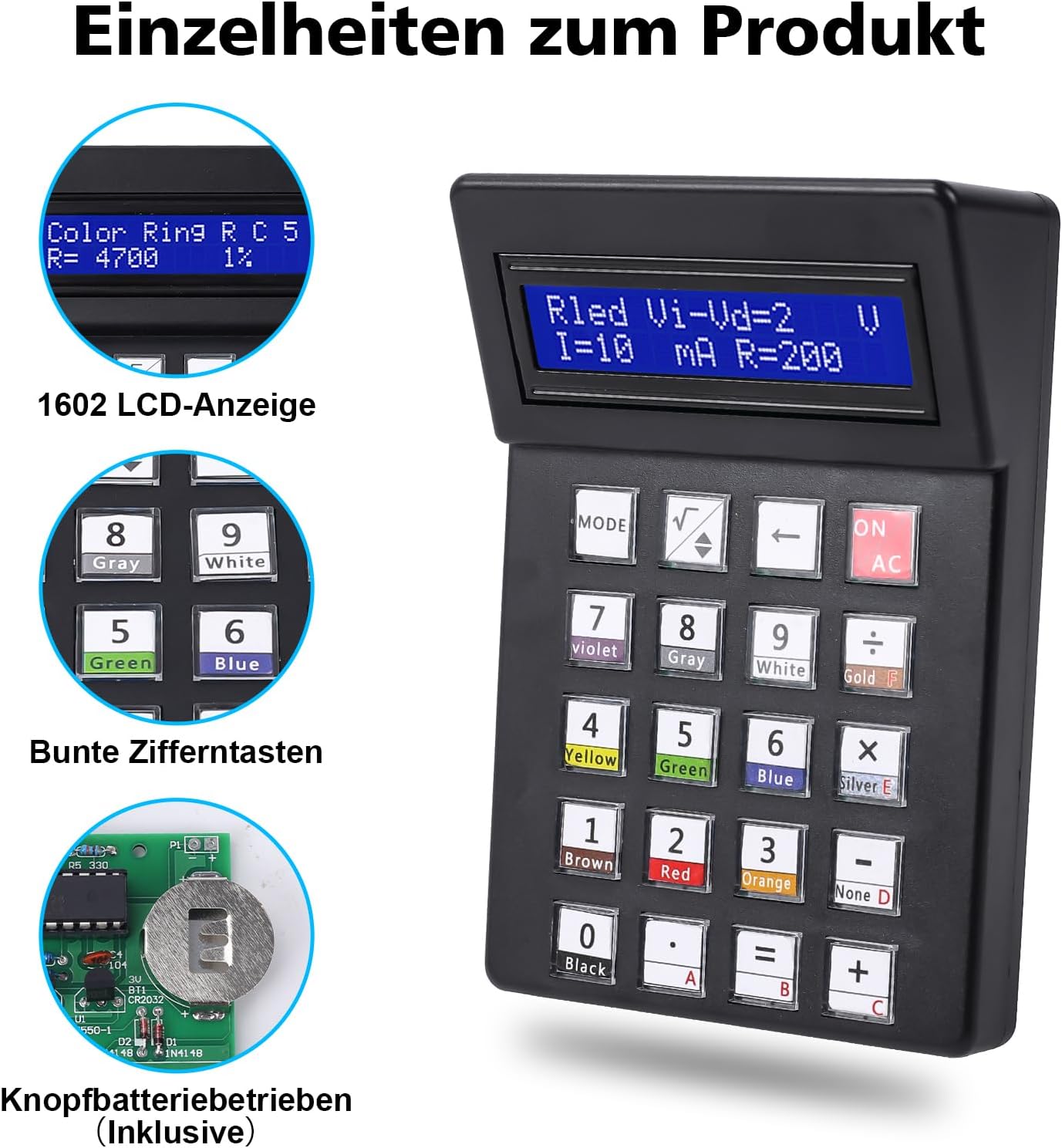
Image 1.1: Main view of the PEMENOL Electronic Soldering Kit Calculator, showcasing its 1602 LCD display and keypad.
2. Safety Information
- Soldering Safety: Always work in a well-ventilated area. Use appropriate safety gear, such as safety glasses, to protect your eyes from solder splashes. Be aware that soldering irons reach high temperatures and can cause burns.
- Electrical Safety: Ensure all components are correctly oriented before soldering to prevent short circuits or damage.
- Battery Safety: The kit uses a Lithium Polymer battery. Handle batteries with care. Do not short-circuit, disassemble, or expose to extreme temperatures. Dispose of batteries responsibly.
- Adult Supervision: This kit is recommended for users with basic electronic knowledge and soldering skills. Adult supervision is advised for younger users.
3. Package Contents
Before beginning assembly, verify that all components listed below are present in your package. The kit includes paper instructions for assembly, which can be followed alongside this manual.

Image 3.1: Detailed diagram of all electronic components, screws, PCB, LCD screen, and housing parts included in the kit.
Component List:
- Printed Circuit Board (PCB)
- 1602 LCD Screen
- Tactile Switches (for keypad)
- Keycaps (Blue and Transparent)
- Resistors (various values)
- Diodes (e.g., 1N4148)
- Transistors
- Integrated Circuit (IC)
- IC Socket
- Pin Headers
- Ceramic Capacitors
- CR2032 Battery Holder
- Screws (8mm self-tapping, 7mm self-tapping)
- Upper and Lower Housing Covers
- Lithium Polymer Battery (CR2032 type)
4. Setup and Assembly
The assembly process for this soldering kit is straightforward, with clear markings on the PCB to guide component placement. An estimated soldering time is 2-3 hours. Basic electronic theoretical knowledge and soldering skills are required.
Assembly Steps:
- Prepare Your Workspace: Ensure you have a clean, well-lit, and well-ventilated area. Gather your soldering iron, solder, desoldering wick/pump, and safety glasses.
- Identify Components: Match each component from the package contents list with its corresponding symbol and value on the PCB. It is recommended to start by soldering components with the lowest profile first (e.g., resistors, diodes) and then proceed to taller components (e.g., IC socket, pin headers, switches).
- Solder Components: Carefully insert each component into its designated position on the PCB. Ensure correct polarity for diodes, ICs, and electrolytic capacitors. Solder each pin securely, ensuring good solder joints without bridges.
- Install IC Socket: Solder the IC socket before inserting the actual IC. This protects the IC from heat during soldering.
- Mount LCD Screen: Solder the pin headers to the LCD screen and then to the PCB. Ensure the screen is aligned correctly.
- Install Keypad Switches: Solder the tactile switches onto the PCB. Place the blue and transparent keycaps onto the switches.
- Connect Battery Holder: Solder the CR2032 battery holder to its designated pads on the PCB.
- Insert IC: Once all soldering is complete and the PCB has cooled, carefully insert the IC into its socket, ensuring correct orientation (notch alignment).
- Assemble Housing: Place the assembled PCB into the lower housing cover. Secure the upper housing cover with the provided screws. Insert the Lithium Polymer battery into its holder.

Image 4.1: Example of soldering practice, demonstrating the educational aspect of the kit.

Image 4.2: Schematic diagram illustrating the circuit connections of the calculator kit.
5. Operating Instructions
After successful assembly, your PEMENOL Electronic Soldering Kit Calculator is ready for use. It features a 1602 LCD display for clear readouts and large keys for easy input.

Image 5.1: Close-up of the calculator's display and keypad, highlighting the color-coded number buttons.
Calculator Functions:
- Basic Arithmetic Operations: Perform addition, subtraction, multiplication, and division with decimal and negative numbers.
- Resistor Color Code Decoder: Input resistor color bands to determine their resistance value. This function assists in identifying component specifications.
- Number Base Conversion: Convert numbers between decimal and hexadecimal formats.
- Square Root Calculation: Compute the square root of numbers.
Use the 'MODE' button to switch between different functions as needed. The 'ON/AC' button powers on the device and clears the current calculation.
6. Maintenance
- Cleaning: Use a soft, dry cloth to clean the calculator's exterior. Avoid using abrasive cleaners or solvents, which may damage the plastic or screen.
- Battery Replacement: The calculator is powered by a CR2032 Lithium Polymer battery. When the display dims or the calculator stops functioning, it's time to replace the battery. This requires unscrewing the housing to access the battery holder. Ensure the new battery is inserted with the correct polarity.
- Storage: Store the calculator in a cool, dry place away from direct sunlight and extreme temperatures.
7. Troubleshooting
- Calculator Does Not Power On:
- Check if the battery is correctly inserted and fully charged.
- Verify all power connections on the PCB are properly soldered.
- Display Issues (Blank or Garbled):
- Ensure the LCD screen's pin headers are securely soldered and connected.
- Check for any solder bridges or cold solder joints around the LCD connections or IC.
- Incorrect Calculations:
- Double-check your input.
- Verify that all resistors and other components are of the correct value and installed in their designated positions.
- Buttons Not Responding:
- Inspect the tactile switches and their solder joints for proper connection.
- Ensure keycaps are correctly seated.
If you encounter persistent issues, carefully review the assembly steps and schematic diagram (Image 4.2) to identify any potential errors.
8. Specifications
| Feature | Specification |
|---|---|
| Brand | PEMENOL |
| Model Number | GY21239-333-FBA |
| Product Dimensions | 17 x 12 x 4.5 cm |
| Product Weight | 210 g |
| Batteries | 1 Lithium Polymer (CR2032 type), included |
| Screen Size | 1.6 Inches |
| Screen Type | LCD |
| Power Source | Battery |
| Material | Plastic |
| UPC | 772288338341 |
9. Warranty and Support
For any questions, technical assistance, or warranty inquiries regarding your PEMENOL Electronic Soldering Kit Calculator, please contact PEMENOL customer support through the retailer where the product was purchased. Please provide your model number (GY21239-333-FBA) and a detailed description of your issue for efficient support.


