
AITRIP ESP32-2432S028R
AITRIP ESP32 Development Board User Manual
Model: ESP32-2432S028R | Brand: AITRIP
Introduction
The AITRIP ESP32-2432S028R Development Board is a versatile and powerful module designed for various IoT applications. Featuring a 2.8-inch 240x320 smart display with touch capabilities, it integrates WiFi and Bluetooth connectivity, making it ideal for projects requiring remote control, data collection, and smart device integration. This manual provides essential information for setting up, operating, and maintaining your development board.
Package Contents
Verify that all items listed below are included in your package:
- 2.8-inch LCD TFT Module (ESP32-2432S028R Development Board)
- USB Cable
- Stylus Pen
- Jumper Wires

Image: Contents of the 2-pack, including two ESP32 development boards, USB cables, styluses, and jumper wires.
Key Features
- Integrated Display: 2.8-inch 240x320 smart display with touch functionality for interactive applications.
- Powerful Controller: Based on ESP32-DOWDQ6, featuring a low-power, dual-core CPU with a clock frequency up to 240MHz.
- Connectivity: Built-in WiFi (802.11b/g/n/e/i) and Bluetooth (4.2 BR/EDR and BLE standard) for versatile wireless communication.
- Rich Peripherals: Supports UART, SPI, I2C, PWM, ADC, DAC interfaces.
- Camera Support: Compatible with OV2640 and OV7670 cameras (not included), with built-in flash support.
- Storage: Supports TF card (up to 4GB) for expanded data storage.
- Development Friendly: Embedded Lwip and FreeRTOS, supports STA/AP/STA+AP working modes, Smart Config, AirKiss one-click network configuration, and secondary development.
- Applications: Ideal for home smart devices, wireless monitoring, smart agriculture, QR wireless recognition, and other IoT applications.

Image: The ESP32 development board showcasing its graphical user interface capabilities.
Technical Specifications
| Parameter | Value |
|---|---|
| Working Voltage | 4.75-5.25V |
| SPI Flash | Default 32Mbit |
| Internal RAM | 520KB |
| Wi-Fi Standard | 802.11b/g/n/e/i |
| Bluetooth Standard | 4.2 BR/EDR and BLE |
| Supported Interfaces | UART, SPI, I2C, PWM (2Mbps) |
| TF Card Support | Maximum 4GB |
| IO Ports | 9 |
| Serial Port Rate | Default 115200bps |
| Spectrum Range | 2400 ~ 2483.5MHz |
| Antenna Form | Onboard PCB antenna, gain 2dBi |
| Image Output Format | JPEG (OV2640 only), BMP, GRAYSCALE |
| Operating Temperature | -20℃ ~ 70℃ |
| Storage Environment | -40℃ ~ 125℃, <90%RH |
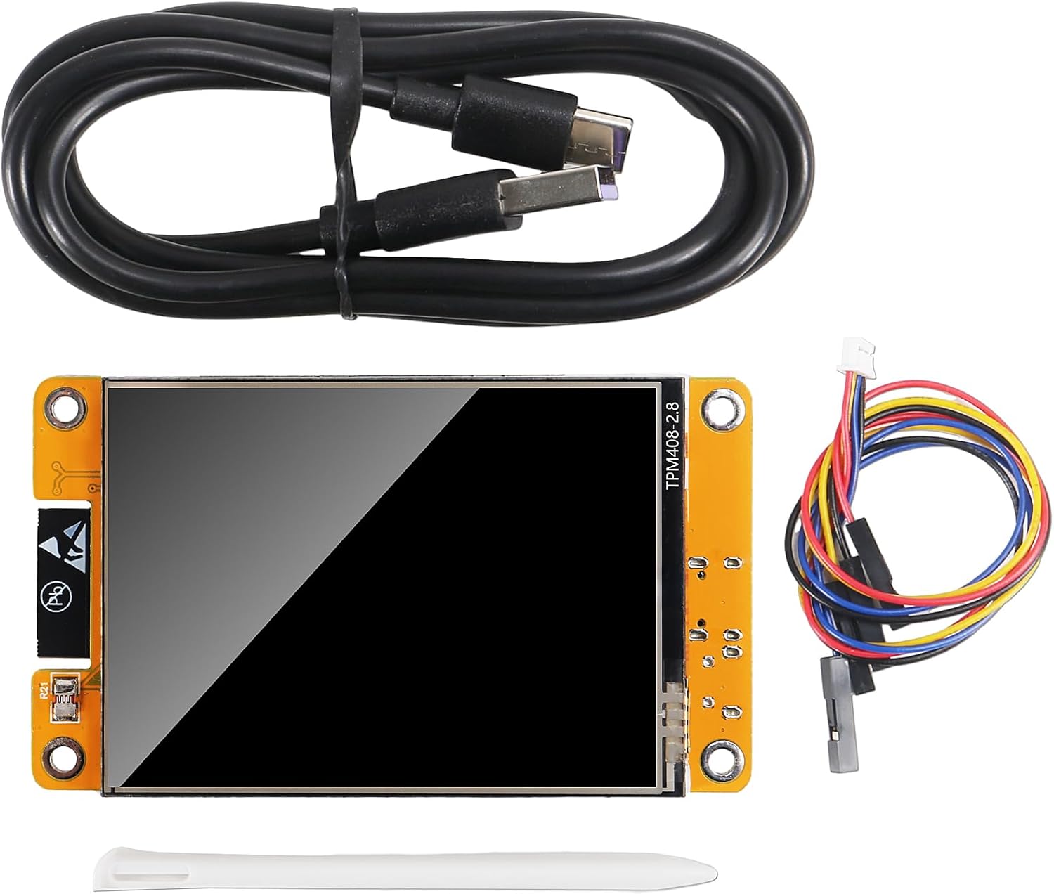
Image: Physical dimensions of the ESP32 development board.

Image: Detailed view of the ESP32 development board with key components and interfaces labeled.
Setup Guide
- Power Connection: Connect the ESP32 development board to your computer using the provided Micro-USB cable. This will power the board and establish a serial communication link.
- Driver Installation: Depending on your operating system, you may need to install USB-to-serial drivers (e.g., CP210x or CH340G drivers) for your computer to recognize the board. Refer to online resources for specific driver installation instructions.
- Development Environment Setup: Install a suitable Integrated Development Environment (IDE) such as Arduino IDE or PlatformIO. Configure the IDE to support ESP32 boards.
- First Program Upload: Once the IDE is set up, you can upload your first program (sketch) to the board. Ensure the correct board type and COM port are selected in your IDE. The board supports automatic download.
- TF Card Insertion (Optional): If your application requires external storage, insert a formatted TF card (up to 4GB) into the designated slot on the board.
Image: Locate the Micro-USB port and TF card slot for initial setup.
Operation
The ESP32-2432S028R board is designed for a wide range of interactive and connected applications:
- Display Interaction: Utilize the 2.8-inch touch screen for user input and displaying information. The display is controllable and can be used for various interactive interfaces.
- Wireless Communication: Leverage WiFi and Bluetooth for remote control, data transmission, and network integration. This includes APP remote control, remote environmental data collection, and remote parameter setting.
- IoT Applications: Implement solutions for home smart devices, wireless monitoring, smart agriculture, and other Internet of Things scenarios.
- Data Storage: Use the TF card slot for logging data, storing images, or managing application resources.
- Power Management: The board supports multiple sleep modes (Deep-sleep, Moderm-sleep, Light-sleep) to optimize power consumption for battery-powered applications.

Image: Demonstrating touch screen interaction with the included stylus.

Image: Conceptual diagram showing the board's integration into an IoT network for data exchange and control.
Maintenance and Care
- Handling: Handle the board by its edges to avoid touching components, especially the screen and exposed circuitry, which can be sensitive to static electricity.
- Cleaning: Use a soft, dry, lint-free cloth to gently wipe the screen and board. Avoid using liquid cleaners or abrasive materials.
- Storage: Store the board in a cool, dry environment, away from direct sunlight, extreme temperatures, and high humidity. Use anti-static bags if available.
- Power Supply: Always use a stable 5V power supply within the specified voltage range (4.75-5.25V) to prevent damage to the board.
- Firmware Updates: Regularly check for and apply firmware updates from the manufacturer or community to ensure optimal performance and security.
Troubleshooting
- Board Not Detected by Computer:
- Ensure the USB cable is securely connected to both the board and the computer.
- Verify that the correct USB-to-serial drivers are installed for your operating system.
- Try a different USB port or cable.
- Program Upload Fails:
- Check if the correct board type (ESP32 Dev Module) and COM port are selected in your IDE.
- Ensure no other application is using the serial port.
- Sometimes, pressing the "BOOT" button while connecting or during upload can help.
- Display Not Working:
- Verify that your code correctly initializes and sends data to the display.
- Ensure the board is receiving adequate power.
- WiFi/Bluetooth Connectivity Issues:
- Check your network credentials (SSID, password) in your code.
- Ensure the board is within range of the WiFi access point or Bluetooth device.
- Verify that the antenna is not obstructed.
Support and Resources
For further assistance, detailed programming guides, and community support, please refer to the following resources:
- Manufacturer's Website: Visit the AITRIP official website for product documentation, drivers, and example code.
- ESP32 Community Forums: Engage with the broader ESP32 developer community for project ideas, troubleshooting tips, and advanced programming techniques.
- Online Tutorials: Many online tutorials and guides are available for getting started with ESP32 development and utilizing its features.
Ask a question about this manual
Ask about setup, troubleshooting, compatibility, parts, safety, or missing instructions. Manuals+ will review the question and use this page’s manual context to help answer it.