
1. Introduction
This manual provides detailed instructions for the installation, operation, and maintenance of your RWRAPS Tm618N-2 Digital Programmable Timer Switch. This device is designed to automatically control the power supply to various electrical equipment according to a preset schedule, offering convenience and energy efficiency. Please read this manual thoroughly before use to ensure proper functionality and safety.
2. Safety Information
- Ensure the power supply is disconnected before installation or maintenance to prevent electric shock.
- This device operates on 220V AC. Incorrect voltage can damage the unit and connected appliances.
- Installation should be performed by a qualified electrician or knowledgeable individual.
- Do not expose the timer to moisture, extreme temperatures, or corrosive environments.
- Do not attempt to disassemble or repair the unit yourself. Contact qualified personnel for service.
- The maximum load capacity must not be exceeded (16A/250VAC or 20A@30VDC).
3. Product Features
- 1.6-inch LCD digital display for clear visibility.
- 7-day programmable timer with up to 16 ON/OFF settings per day.
- Integrated relay for high-power switching.
- Countdown time function.
- Clock correction/calibration function for high accuracy (less than 1s error per day).
- Keyboard lock function to prevent accidental operations.
- Manual ON/OFF override.
- Long-life silicone buttons.
4. Package Contents
Upon opening the package, please verify that all components are present and undamaged.
- 1 x RWRAPS Tm618N-2 Digital Programmable Timer Switch
- 1 x User Manual (this document)
5. Product Overview

Figure 5.1: Front View of the Timer Switch. This image displays the front of the RWRAPS Tm618N-2 timer switch, showing the LCD screen, control buttons (WEEK, HOUR, MIN, RECALL, CLOCK, PROG, MANUAL), and the 'R' reset button. The screen shows "MO AM 6:18 18 AUTO".
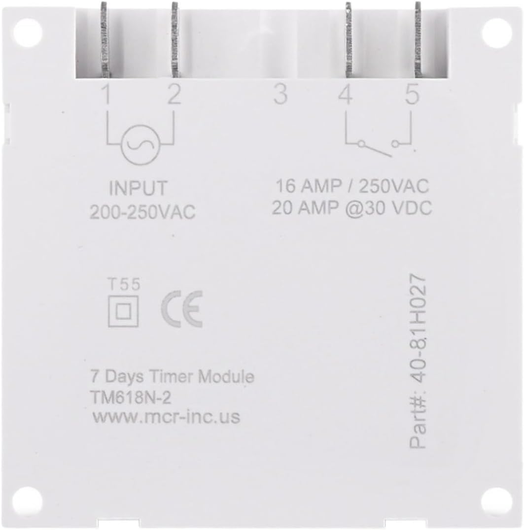
Figure 5.2: Back View and Wiring Diagram. This image shows the rear of the timer switch, detailing the input and output terminals. It indicates "INPUT 200-250VAC" on terminals 1 and 2, and "16 AMP / 250VAC, 20 AMP @30 VDC" on terminals 4 and 5, which are the relay contacts. Terminal 3 is not used. The model number "TM618N-2" is also visible.
6. Installation and Wiring
Important: Ensure power is disconnected before proceeding with installation. Incorrect wiring can cause damage or injury. If you are unsure, consult a qualified electrician.
- Mounting: The timer switch is designed for panel mounting or DIN rail mounting (if an adapter is used, not included). Secure the unit in a suitable enclosure or panel.
- Power Input (200-250VAC): Connect the live (L) and neutral (N) wires of your 220V AC power supply to terminals 1 and 2 on the back of the timer. Refer to Figure 5.2.
- Load Output (Relay Contacts):
- Connect the live wire from your load (e.g., light, fan) to terminal 4.
- Connect the live wire from your power source (the same 220V AC supply or a separate DC supply) to terminal 5.
- The neutral wire of your load should be connected directly to the neutral of your power source, bypassing the timer switch.
Note: Terminals 4 and 5 are dry contacts (voltage-free relay contacts). They can switch either AC (up to 250V, 16A) or DC (up to 30V, 20A) loads. Ensure your load's power requirements do not exceed these ratings. Terminal 3 is not used.
- Initial Power-Up: After wiring, restore power. The LCD screen should illuminate. If it does not, check your wiring.
7. Operating Instructions
7.1. Initial Setup and Clock Setting
- Reset: Press the 'R' button (recessed, use a pointed object) to clear all settings and reset the timer. The display will show "0:00".
- Set Current Time:
- Press and hold the CLOCK button.
- While holding CLOCK, press WEEK to set the current day of the week (MO, TU, WE, TH, FR, SA, SU).
- While holding CLOCK, press HOUR to set the current hour (0-23 for 24-hour format).
- While holding CLOCK, press MIN to set the current minute (0-59).
- 12/24 Hour Format: Press CLOCK and PROG simultaneously to toggle between 12-hour (AM/PM) and 24-hour formats.
7.2. Programming ON/OFF Times
The timer allows for up to 16 ON/OFF programs.
- Press the PROG button once. The display will show "1 ON" and the time will flash.
- Press WEEK to select the day(s) for this program. You can choose a single day, weekdays, weekends, or various combinations.
- Press HOUR to set the desired ON hour.
- Press MIN to set the desired ON minute.
- Press PROG again. The display will show "1 OFF" and the time will flash.
- Repeat steps 2-4 to set the desired OFF time for the first program.
- Press PROG to cycle through "2 ON", "2 OFF", and so on, up to "16 OFF". Repeat the setting process for each desired program.
- To exit programming mode, press the CLOCK button.
Note: If you need to cancel a program, press RECALL while viewing the specific ON or OFF program. This will replace the time with "--:--", effectively disabling that program step.
7.3. Manual Override
Press the MANUAL button to cycle through the following modes:
- AUTO ON: The timer is currently ON and will follow the programmed OFF times.
- AUTO OFF: The timer is currently OFF and will follow the programmed ON times.
- ON: The timer output is continuously ON, overriding all programs.
- OFF: The timer output is continuously OFF, overriding all programs.
For automatic operation, ensure the timer is set to either "AUTO ON" or "AUTO OFF".
7.4. Countdown Function
The countdown function allows you to set a specific duration after which the timer will switch its state (ON to OFF, or OFF to ON).
- While in normal clock display mode, press and hold the PROG button for approximately 3 seconds. The display will show "d ON" or "d OFF" and the time will flash.
- Press HOUR and MIN to set the desired countdown duration (up to 99 hours and 59 minutes).
- Press PROG again to start the countdown. The display will show the remaining time.
- To cancel the countdown, press PROG again.
8. Maintenance
- Keep the timer switch clean and free from dust. Use a soft, dry cloth for cleaning.
- Do not use abrasive cleaners or solvents.
- Periodically check wiring connections to ensure they are secure.
- The internal battery (for timekeeping during power outages) is not user-replaceable. If the timer loses time frequently, the battery may need professional service.
9. Troubleshooting
| Problem | Possible Cause | Solution |
|---|---|---|
| Display is blank. | No power supply; internal battery depleted. | Check power connections. If power is present, the internal battery may need charging (leave connected to power for several hours) or replacement (professional service). |
| Timer does not switch ON/OFF as programmed. | Incorrect program settings; timer in manual ON/OFF mode; incorrect wiring. | Verify program settings (ON/OFF times, days). Ensure the timer is in "AUTO ON" or "AUTO OFF" mode. Check wiring connections. |
| Time is inaccurate. | Internal clock drift; internal battery issue. | Reset and re-set the clock. If the issue persists, the internal battery may be failing. |
| Buttons are unresponsive. | Keyboard lock engaged; unit malfunction. | Press and hold CLOCK for 3 seconds to unlock the keyboard. If still unresponsive, try resetting the unit. |
10. Technical Specifications
| Model | Tm618N-2 |
| Brand | RWRAPS |
| Input Voltage | 200-250VAC |
| Output (Relay) Capacity | 16A / 250VAC, 20A @ 30VDC |
| Programmable Cycles | 16 ON/OFF programs per day/week |
| Display | 1.6-inch LCD |
| Time Error | Less than 1 second per day |
| Material | Plastic |
| Weight | Approx. 200 Grams (7.1 ounces) |
11. Warranty Information
As per product specifications, this RWRAPS Tm618N-2 Digital Programmable Timer Switch comes with No Warranty. Please refer to your retailer's return policy for details on product returns or exchanges.
12. Customer Support
For any questions, technical assistance, or issues not covered in this manual, please contact your product retailer or the manufacturer, RWRAPS, through their official support channels.