
BSIDE
BSIDE A1X Digital Multimeter User Manual
Model: A1X Smart Multimeter with Case
1. Introduction
The BSIDE A1X is a compact and intelligent digital multimeter designed for easy and accurate electrical measurements. It features automatic function recognition, a clear LCD display with red and green backlight, non-contact voltage detection, and a built-in rechargeable battery. This manual provides detailed instructions for safe and effective use of your multimeter.
2. Safety Information
Always observe basic safety precautions when using this multimeter to avoid personal injury or damage to the device. Read all instructions carefully before use.
- Do not exceed the maximum input values specified for each measurement range.
- Exercise extreme caution when working with voltages above 30V AC RMS, 42V peak, or 60V DC. Such voltages pose a shock hazard.
- Before measuring current, ensure the multimeter is connected in series with the load and the correct function is selected.
- Before measuring resistance, continuity, diode, or capacitance, ensure the circuit is de-energized and all capacitors are discharged.
- Do not use the multimeter if it appears damaged or if the test leads are damaged.
- Always use the correct terminals, function, and range for your measurement.
- Keep hands and fingers behind the probe barriers during measurements.
- Do not operate the multimeter in explosive gas, vapor, or dust environments.
- Refer to the specifications section for detailed measurement limits.
3. Package Contents
Verify that all items are present in your package:
- BSIDE A1X Digital Multimeter
- Test Leads (Red and Black)
- USB Charging Cable
- Protective Case
- User Manual (English)

Figure 3.1: Contents of the BSIDE A1X Multimeter package. The image shows the multimeter, red and black test leads, a USB charging cable, and a black protective case.
4. Product Features
- Smart Measurement: Automatically measures AC/DC voltage, resistance, and continuity.
- Clear Display: LCD screen with red and green backlight for intuitive visual feedback.
- Non-Contact Voltage (NCV) Detection: Detects AC voltage without direct contact (6V-1000V / 90V-1000V).
- Live Wire Check: Identifies live and neutral wires.
- Capacitance and Diode Test: Expanded functionality for electronic component testing.
- Rechargeable Battery: Built-in 3.7V 400mA rechargeable Lithium-ion battery.
- LED Flashlight: Integrated flashlight for working in low-light conditions.
- Auto Power Off: Conserves battery life.
- Low Battery Indication: Alerts when battery is low.
- Compact Design: Mini pocket-sized tester for portability.

Figure 4.1: The bright LED flashlight feature of the BSIDE A1X Multimeter, useful for illuminating work areas.
5. Setup
5.1 Charging the Battery
The BSIDE A1X Multimeter comes with a built-in rechargeable Lithium-ion battery. Before first use, or when the low battery indicator appears, charge the device using the provided USB charging cable.
- Connect the small end of the USB charging cable to the charging port on the multimeter.
- Connect the other end of the USB cable to a standard USB power adapter (e.g., phone charger, computer USB port).
- The charging indicator light will show the charging status. Once fully charged, the light may change color or turn off.

Figure 5.1: The BSIDE A1X Multimeter being charged via its USB port, indicating its rechargeable battery feature.
5.2 Connecting Test Leads
For most measurements, you will need to connect the test leads to the multimeter.
- Insert the black test lead into the "COM" (Common) input jack.
- Insert the red test lead into the "INPUT" jack.
- Ensure the connections are firm and secure before taking any measurements.
6. Operating Instructions
6.1 Power On/Off
Press and hold the power button (ⓘ) to turn the multimeter on or off.
6.2 Automatic Mode (AUTO)
Upon powering on, the multimeter defaults to Automatic Mode. In this mode, the device intelligently identifies and measures AC/DC voltage, resistance, and continuity without manual range selection.

Figure 6.1: The multimeter's display indicating the automatic mode selection, where it can detect and measure AC/DC voltage, resistance, continuity, NCV, and Live functions.
6.3 Manual Mode Selection
Press the "AUTO SEL" button to cycle through manual measurement functions: Voltage (AC/DC), Resistance (Ω), Diode, Capacitance, and Continuity. The selected function will be indicated on the display.
6.4 Voltage Measurement (AC/DC)
To measure voltage:
- Ensure test leads are connected correctly (Black to COM, Red to INPUT).
- If not in Auto mode, press "AUTO SEL" until the voltage icon (V) is displayed.
- Connect the test probes in parallel to the circuit or component you wish to measure.
- Read the voltage value on the display. The display will show "DC" or "AC" to indicate the type of voltage.

Figure 6.2: The multimeter being used for household troubleshooting, specifically measuring voltage within an electrical panel.
6.5 Resistance Measurement (Ω)
To measure resistance:
- Ensure the circuit is de-energized.
- If not in Auto mode, press "AUTO SEL" until the resistance icon (Ω) is displayed.
- Connect the test probes across the component or circuit where you want to measure resistance.
- Read the resistance value on the display.
6.6 Continuity Test
To test for continuity:
- Ensure the circuit is de-energized.
- If not in Auto mode, press "AUTO SEL" until the continuity icon (⦁)) is displayed.
- Connect the test probes across the circuit or component.
- If resistance is less than 50Ω, the buzzer will sound, indicating continuity.
6.7 Diode Test
To test a diode:
- Ensure the diode is disconnected from any power source.
- If not in Auto mode, press "AUTO SEL" until the diode icon (➟|△) is displayed.
- Connect the red probe to the anode and the black probe to the cathode of the diode.
- Read the forward voltage drop on the display. Reverse the probes; an open circuit (OL) reading indicates a good diode.

Figure 6.3: The multimeter being used for electronic maintenance, demonstrating its capability to test components like capacitors and diodes on a circuit board.
6.8 Capacitance Measurement
To measure capacitance:
- Ensure the capacitor is fully discharged before testing.
- If not in Auto mode, press "AUTO SEL" until the capacitance icon (—||—) is displayed.
- Connect the test probes across the capacitor terminals.
- Read the capacitance value on the display.
6.9 Non-Contact Voltage (NCV) Detection
The NCV function allows detection of AC voltage without direct contact with wires.
- Press the "V-Alert" button to activate NCV mode.
- Move the top tip of the multimeter close to the wire or outlet.
- The display will show "NCV" and the backlight will turn red, accompanied by a buzzer sound, indicating the presence of AC voltage. The intensity of the beeps and light indicates signal strength.
- Press the "V-Alert" button again to adjust sensitivity (High/Low).
Video 6.1: Demonstration of the Live/Zero wire detection by contact using the BSIDE A1X Multimeter. The video shows the multimeter's display changing color and emitting sound when detecting live voltage.
6.10 Live Wire Check
This function helps identify live (phase) and neutral wires.
- Press "AUTO SEL" until the "LIVE" icon is displayed.
- Insert the red test probe into the socket or touch the wire.
- If it's a live wire, the display will turn red, show "LIVE", and the buzzer will sound. For a neutral wire, the display will remain green and show "NEU".
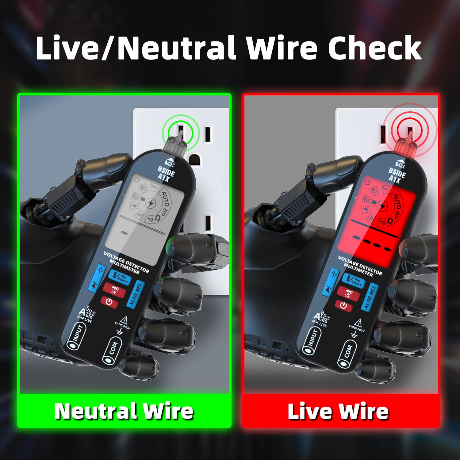
Figure 6.4: The multimeter's display indicating the detection of a Neutral Wire (green backlight) versus a Live Wire (red backlight), providing clear visual feedback.
Video 6.2: A comprehensive demonstration of the BSIDE A1X Mini automatic multimeter tester's various functions, including voltage, resistance, continuity, diode, and capacitance measurements.
6.11 Display Backlight
The multimeter features a red and green backlight. The green backlight indicates normal operation, while the red backlight often indicates a high voltage detection (above 90V) or a live wire detection.

Figure 6.5: The multimeter's display demonstrating both red and green backlight options, providing visual cues for different measurement states.
7. Maintenance
7.1 Cleaning
Wipe the case with a damp cloth and mild detergent. Do not use abrasives or solvents. Ensure the device is off and disconnected from any power source before cleaning.
7.2 Battery Care
To prolong battery life, charge the multimeter regularly, especially if it has not been used for an extended period. Avoid fully discharging the battery frequently.
7.3 Storage
When not in use, store the multimeter in its protective case in a cool, dry place, away from direct sunlight and extreme temperatures.
8. Troubleshooting
| Problem | Possible Cause | Solution |
|---|---|---|
| Multimeter does not turn on. | Low or discharged battery. | Charge the battery using the USB cable. |
| Inaccurate readings. | Incorrect function selected; poor test lead connection; external interference. | Ensure correct function is selected (or use Auto mode); check test lead connections; move away from strong electromagnetic fields. |
| "OL" (Overload) displayed. | Measurement exceeds the range; open circuit. | Ensure the measured value is within the multimeter's range; check for open circuits in continuity/resistance tests. |
| NCV/Live detection not working. | No voltage present; low sensitivity setting. | Verify voltage presence; try increasing NCV sensitivity. |
9. Specifications
| Parameter | Value |
|---|---|
| Display | 2000 Counts, LCD Backlit (Red/Green) |
| DC Voltage | 0-520V, 0.001V resolution, ±(0.8%+3) accuracy |
| AC Voltage | 0-520V, 0.001V resolution, ±(0.8%+3) accuracy |
| Resistance | 0Ω-19.99MΩ, 1Ω resolution, ±(1.2%+3) accuracy |
| Diode | Measures diodes less than 3V |
| Capacitance | 1nF-1999nF (0.01nF res, ±(3.5%+8) acc), 2µF-1999µF (0.01µF res, ±(4.5%+10) acc) |
| Continuity | Buzzer sounds if resistance is less than 50Ω |
| V-Alert (NCV) | AC Voltage 90V-1000V / 6V-1000V |
| Live Wire Check | Yes |
| Power Supply | 3.7V 400mA Rechargeable Battery |
| Dimensions | 146 x 44 x 25 mm (5.75 x 1.73 x 0.98 inches) |
| Weight | 73g (2.57 oz) |
| Safety Compliance | CE, CAT III 600V |
10. Warranty and Support
BSIDE products are manufactured to high quality standards. For warranty information, technical support, or service inquiries, please refer to the contact details provided with your purchase or visit the official BSIDE website. Keep your purchase receipt as proof of purchase.
Related documents


Ask a question about this manual
Ask about setup, troubleshooting, compatibility, parts, safety, or missing instructions. Manuals+ will review the question and use this page’s manual context to help answer it.