
1. Introduction
The Hantek USB/PC Portable Oscilloscope Hantek6074BD is a versatile 4-channel device designed for various electrical testing and measurement applications. It offers performance comparable to benchtop oscilloscopes in a compact, portable form factor. This device features a USB2.0 interface for plug-and-play connectivity with portable computers and tablet PCs, making it ideal for field use, production line testing, and repair work.
Key functionalities include pass/fail testing, a resourceful trigger function, dynamic cursor tracking, and waveform recording. It also integrates a DDS/Arb Waveform Generator for comprehensive signal analysis.
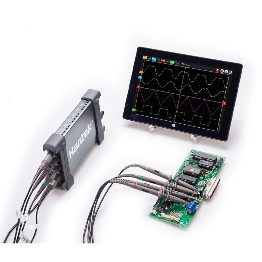
Figure 1.1: Hantek USB/PC Oscilloscope in operation, connected to a tablet and a circuit board.
2. What's in the Box
Upon unpacking your Hantek6074BD Oscilloscope kit, please verify that all the following components are present:
- Hantek6074BD USB/PC Oscilloscope Unit
- 2 Passive Probes
- 2 Gator Clip Lines
- 1 BNC to BNC Cord
- USB Cable
- Software CD (or download link)
- User Manual (this document)

Figure 2.1: Hantek6074BD Oscilloscope kit contents.
3. Setup
Follow these steps to set up your Hantek USB/PC Oscilloscope:
- Software Installation: Insert the provided software CD into your computer's CD-ROM drive, or download the latest software from the official Hantek website (www.hantek.com). Follow the on-screen instructions to install the necessary drivers and application software. The software supports Windows 2000/XP/Vista/Win7/Win8 operating systems.
- Connect USB Cable: Connect the USB cable from the oscilloscope unit to an available USB 2.0 port on your PC or tablet. The device is plug-and-play, and your operating system should recognize it automatically after driver installation.
- Power On: The oscilloscope is powered via the USB connection. Once connected, the device should power on.
- Connect Probes: Attach the passive probes to the BNC input channels (CH1, CH2, CH3, CH4) on the front of the oscilloscope. Ensure a secure connection.
- Connect to Circuit: Connect the probe tips and ground clips to the circuit you intend to measure. Refer to the probe's specifications for proper attenuation settings (e.g., x1, x10).

Figure 3.1: Front panel with BNC input channels.
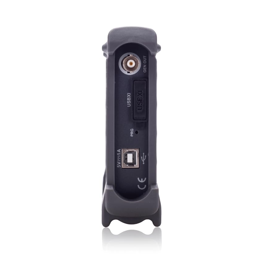
Figure 3.2: Rear panel with USB connection and waveform generator output.
Video 3.1: A brief demonstration of connecting the Hantek USB/PC Oscilloscope to a power source and observing the indicator light. This video shows the physical connections and initial power-up sequence of the device.
4. Operating the Oscilloscope
Once the hardware is connected and software is installed, launch the Hantek oscilloscope application on your computer. The software provides a graphical user interface (GUI) to control the oscilloscope functions and display waveforms.
4.1 Basic Measurements
- Channel Selection: Enable or disable channels (CH1-CH4) as needed within the software.
- Vertical Scale (Volts/Div): Adjust the vertical scale to fit the signal amplitude on the screen.
- Horizontal Scale (Time/Div): Adjust the horizontal scale to view the signal's period or frequency.
- Trigger Settings: Configure the trigger mode (Edge, Pulse, Video, Alternative), trigger source (CH1-CH4), and trigger level to stabilize the waveform display.
- Auto-setup: Utilize the auto-setup function for quick configuration of vertical and horizontal scales, and trigger settings.
4.2 Advanced Features
- Pass/Fail Test: Set up criteria for waveform comparison to automatically identify signals that fall outside defined limits.
- Dynamic Cursor Tracking: Use cursors to precisely measure voltage and time parameters on the waveform.
- Waveform Record: Capture and save waveforms for later analysis.
- DDS/Arb Waveform Generator: Use the integrated waveform generator to output various signal types (Sine, Square, Triangle, etc.) for testing circuits.
- Waveform Process: Apply mathematical operations (+, -, x, ÷, FFT, Invert) to waveforms for deeper analysis.
- Export Data: Waveforms and measurement data can be exported to formats like Excel or Word for reporting and documentation.
5. Maintenance
Proper maintenance ensures the longevity and accuracy of your Hantek Oscilloscope:
- Cleaning: Use a soft, dry cloth to clean the exterior of the device. Avoid using abrasive cleaners or solvents that could damage the casing.
- Storage: Store the oscilloscope in a cool, dry place away from direct sunlight and extreme temperatures. When not in use, disconnect all probes and cables.
- Probe Care: Handle probes carefully. Avoid bending or stressing the cables. Regularly check probe tips for damage and replace if necessary.
- Software Updates: Periodically check the Hantek website for software and firmware updates to ensure optimal performance and access to new features.
- Environmental Considerations: The device is designed for indoor use. Avoid exposure to moisture, dust, and corrosive environments.
6. Troubleshooting
If you encounter issues with your Hantek Oscilloscope, refer to the following common problems and solutions:
- Device Not Recognized by PC:
- Ensure the USB cable is securely connected to both the oscilloscope and the PC.
- Verify that the drivers are correctly installed. Reinstall drivers if necessary.
- Try connecting to a different USB port or a different PC to rule out port or PC issues.
- No Waveform Display:
- Check if the probes are correctly connected to the input channels and the circuit under test.
- Adjust the vertical (Volts/Div) and horizontal (Time/Div) scales to appropriate ranges for your signal.
- Verify trigger settings. An unstable or incorrect trigger can prevent a clear waveform display. Try using the auto-setup function.
- Ensure the input signal is within the device's voltage limits (Max 35V peak-to-peak).
- Inaccurate Measurements:
- Perform probe compensation if using passive probes.
- Check the probe attenuation setting (x1, x10) in both the physical probe and the software.
- Ensure proper grounding of the oscilloscope and the circuit.
- Software Crashing or Freezing:
- Ensure your operating system meets the minimum requirements.
- Close other demanding applications.
- Update the software to the latest version from the Hantek website.
7. Specifications
The Hantek6074BD model offers the following technical specifications:
| Feature | Specification (Hantek6074BD) |
|---|---|
| Bandwidth | 70MHz |
| Channel | 4 CH |
| Real-time Sampling Rate | 1GSa/s |
| Memory Depth | 64K |
| Time Base Precision | ±50ppm |
| Time Base Range | 2ns/div-1000s/div (1-2-4 sequences) |
| Input Impedance | 1MΩ 25pF |
| Input Sensitivity | 2mV/div ~ 10V/div |
| Vertical Resolution | 8Bit |
| Vertical Displacement Range | 2mV ~ 10V/div @ x1 probe; 200mV ~ 1000V/div @ x100 probe; ±2V ~ 1000V/div @ x1000 probe |
| DC Gain Accuracy | ±3% |
| Bandwidth Limit | 20MHz |
| Trigger Mode | Edge, Pulse, Video, Alternative |
| Trigger Source | CH1, CH2, CH3, CH4 |
| Waveform Signal Process | +, -, x, ÷, FFT, Invert |
| Cursors | Cross, Trace, Horizontal, Vertical |
| Measurement | Vpp, Vamp, Vmax, Vmin, Vtop, Vmid, Vbase, Vavg, Vrms, Vcrms, Preshoot, Overshoot, Frequency, Period, Rise Time, Fall Time, Positive Width, Negative Width, Duty Cycle |
| Arbitrary Waveform Generator Mode | |
| Waveform | DC~25MHz |
| Frequency | 2K~200MHz adjustable |
| Resolution | 0.10% |
| Channel | 1CH waveform output |
| Waveform Depth | 2KSa |
| Vertical Resolution | 12 bit |
| Frequency Stability | <30ppm |
| Wave Amplitude | ±3.5V Max. |
| Output Impedance | 50 Ω |
| Output Current | 50mA, Ipeak=50mA |
| System BW | 25M |
| Harmonic Distortion | -50dBc(1KHz), -40dBc(10KHz) |
| General Features | |
| Volume | 175mm * 105mm * 25mm |
| Weight | 0.9KG |
| Accessory | 2 passive probes, 2 gator clip lines, 1 BNC to BNC cord |
For a comparison of different Hantek models, refer to the table below:
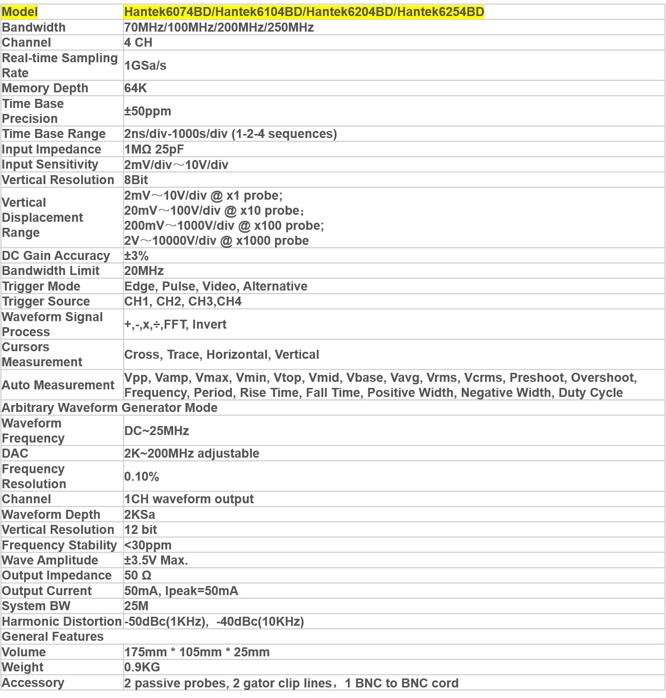
Figure 7.1: Detailed specifications table for various Hantek oscilloscope models.
8. Warranty Information
Hantek products are typically covered by a manufacturer's warranty against defects in materials and workmanship. The specific terms and duration of the warranty may vary by region and product. Please retain your proof of purchase for warranty claims.
For detailed warranty information, please visit the official Hantek website or contact customer support.
9. Customer Support
For technical assistance, troubleshooting, or general inquiries regarding your Hantek USB/PC Portable Oscilloscope, please refer to the following resources:
- Official Website: Visit the Hantek official website for product information, software downloads, FAQs, and support contact details.
- Online Resources: Check for online forums or communities where users share tips and solutions.
When contacting support, please have your product model (Hantek6074BD) and serial number (if applicable) ready. The serial number can often be found on a label on the device itself or on the product packaging.

Figure 9.1: Example of product label with QR code and model information on packaging.