1. Introduction
This manual provides detailed instructions for the safe and effective use of your Proster Clamp Meter Tester (Model PST242). This versatile device is designed for a wide range of electrical measurements, including AC/DC voltage, AC/DC current, resistance, capacitance, frequency, diode testing, continuity, temperature, and non-contact voltage (NCV) detection. It features True RMS measurement for accuracy and an auto-ranging function for ease of use. Please read this manual thoroughly before operation and retain it for future reference.
2. Safety Information
Always adhere to safety precautions when using electrical testing equipment. Failure to do so may result in injury or damage to the device. This clamp meter is certified to CAT II 300V and CAT II 600V standards and carries CE certification.
- Read and understand all instructions before use.
- Do not exceed the maximum input values for any function.
- Inspect test leads and the meter for any damage before each use. Do not use if damaged.
- Ensure the function switch is in the correct position for the desired measurement.
- Use caution when working with voltages above 30V AC RMS, 42V peak, or 60V DC, as these pose a shock hazard.
- Replace batteries when the low battery indicator appears to ensure accurate readings.
3. Product Overview
3.1. Components
The Proster Clamp Meter Tester (Model PST242) package includes the following items:
- Proster Clamp Meter Tester (Model PST242)
- K-type thermocouple
- Test leads (red and black)
- Alligator clips
- 1.5V AAA batteries (3 pieces)
- User manual
- Cloth pouch
- Screwdriver

3.2. Device Layout
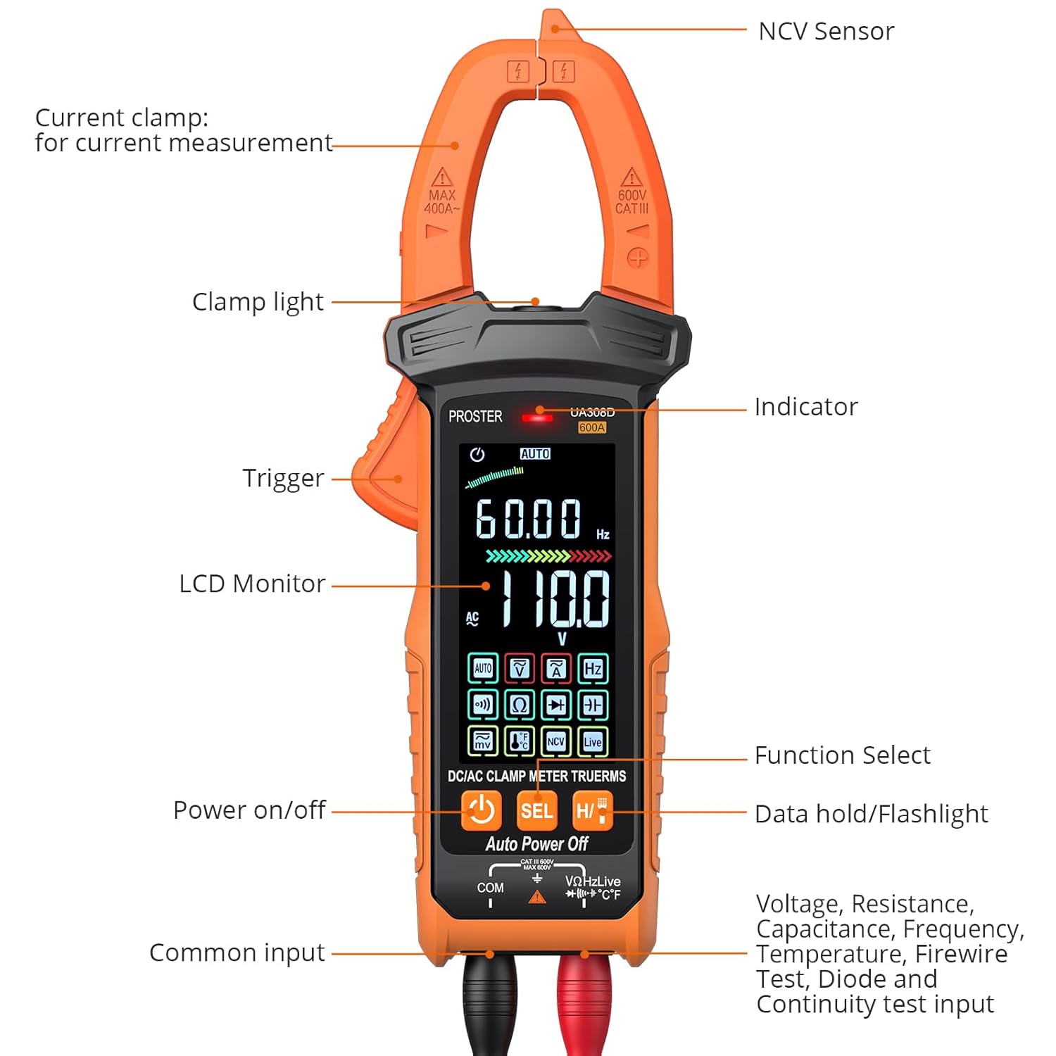
The clamp meter features an intuitive design for ease of use. Key components include:
- Current Clamp: Used for non-contact AC/DC current measurement.
- NCV Sensor: Detects non-contact voltage.
- Clamp Light: Illuminates the measurement area.
- Trigger: Opens the current clamp jaws.
- LCD Monitor: Large, colorful display for readings.
- Power On/Off Button: Controls device power.
- Function Select Button (SEL): Cycles through sub-functions within a mode.
- Data Hold / Flashlight Button (H/T): Holds the current reading or activates the flashlight.
- Input Jacks: For connecting test leads (Common, Voltage/Resistance/etc.).
3.3. Display
The device features a large HD color screen with an analog bar display, providing clear and easy-to-read measurements even in low-light conditions. The display shows measurement values, units, selected functions, and other relevant indicators.

4. Setup
4.1. Battery Installation
The meter requires three 1.5V AAA batteries (included). To install or replace batteries, open the battery compartment cover on the back of the device using the provided screwdriver. Insert the batteries, observing correct polarity, then close the cover securely.
4.2. Connecting Test Leads
For most measurements (voltage, resistance, capacitance, diode, continuity, temperature), connect the red test lead to the 'VΩHz' input jack and the black test lead to the 'COM' input jack. Ensure connections are firm.
5. Operating Modes
The Proster Clamp Meter Tester offers multiple measurement functions. The intelligent auto mode automatically identifies common measurements, while specific modes can be selected for specialized tests.
5.1. Auto Intelligent Mode
When the meter is powered on, it defaults to intelligent mode. In this mode, the meter automatically identifies and measures AC/DC voltage, resistance, and continuity without manual range selection.
5.2. AC/DC Voltage Measurement
To measure voltage, connect the test leads as described in Section 4.2. The meter will automatically detect AC or DC voltage in intelligent mode. For specific voltage types, rotate the dial to the voltage function and use the SEL button to switch between AC and DC if necessary. Apply the test probes to the circuit points to be measured.


5.3. AC/DC Current Measurement
For AC/DC current measurement, use the current clamp. Press the trigger to open the jaws and clamp around a single conductor. The meter can measure up to 600A. Ensure the conductor is centered within the clamp for accurate readings. This is a non-contact method for current measurement.

5.4. Resistance, Capacitance, Frequency, Diode, and Continuity
These functions are typically accessed by rotating the dial to the appropriate symbol and using the SEL button to cycle through related measurements if they share a dial position. Connect the test leads to the component or circuit under test.
- Resistance: Measures electrical resistance in Ohms (Ω).
- Capacitance: Measures capacitance in Farads (F).
- Frequency: Measures frequency in Hertz (Hz).
- Diode Test: Checks the forward voltage drop of a diode.
- Continuity Test: Indicates a continuous electrical path with an audible buzzer.
5.5. Temperature Measurement
Connect the K-type thermocouple to the input jacks. Rotate the dial to the temperature function. Insert the thermocouple probe into the environment or surface to be measured. The display will show the temperature in Celsius (°C) or Fahrenheit (°F).
5.6. NCV (Non-Contact Voltage) and LIVE Functions
The NCV function allows for detection of AC voltage without physical contact. Position the NCV sensor near a live AC voltage source. The meter will indicate the presence of voltage with visual (LED indicator) and audible (buzzer) signals. The LIVE function provides live wire detection, often indicating the phase wire in an AC circuit.

5.7. Data Hold and Flashlight
Press the H/T button briefly to hold the current reading on the display. Press and hold the H/T button to activate the built-in flashlight, useful for illuminating dark work areas.

5.8. General Operation Video
This video provides a general overview of clamp meter functions and usage, demonstrating various measurement capabilities.
6. Maintenance
Proper maintenance ensures the longevity and accuracy of your device.
- Cleaning: Wipe the meter with a dry, soft cloth. Do not use abrasives or solvents.
- Battery Replacement: Replace batteries promptly when the low battery indicator appears. Remove batteries if the meter will not be used for an extended period.
- Storage: Store the meter in a cool, dry place, away from direct sunlight and extreme temperatures. Use the provided cloth pouch for protection.
7. Troubleshooting
If you encounter issues with your clamp meter, refer to the following common problems and solutions:
- No Display: Check battery installation and charge level. Replace batteries if necessary.
- Incorrect Readings: Ensure test leads are properly connected and the correct function is selected. Verify the component being tested is within the meter's measurement range.
- Buzzer Not Working: Check if the continuity function is selected and if the circuit is indeed continuous.
- NCV/LIVE Not Responding: Ensure the function is selected and the sensor is positioned correctly near a live AC source.
For persistent issues, contact customer support.
8. Specifications
| Specification | Value |
|---|---|
| Manufacturer | Proster |
| Part Number | PST242 |
| Item Weight | 22 g |
| Package Dimensions | 22.6 x 14.3 x 7.5 cm |
| Batteries | 3 AAA batteries (included) |
| Measurement Accuracy | ±(0.5%+3) |
| Safety Compliance | CE, CAT II 300V, CAT II 600V |
| Maximum Temperature Rating | 150 °C |
9. Warranty and Support
Specific warranty details and support contact information are not provided in the current product data. Please refer to the product packaging or the manufacturer's official website for the most up-to-date warranty terms and customer support contacts.


