
1. Introduction
This user manual provides comprehensive instructions for the safe and efficient operation of your Hantek DSO2D10 Digital Storage Oscilloscope. Please read this manual thoroughly before using the device to ensure proper functionality and to prevent damage.
2. Safety Information
Always observe the following safety precautions to avoid personal injury and prevent damage to the instrument or other connected devices.
- Use the correct power cord.
- Connect and disconnect probes properly.
- Ground the instrument.
- Observe all terminal ratings.
- Do not operate in wet or damp conditions.
- Do not operate in explosive atmospheres.
- Keep product surfaces clean and dry.
- Refer servicing to qualified personnel.
3. Package Contents
Verify that all items listed below are included in your package. If any items are missing or damaged, please contact your dealer.

Image: The Hantek DSO2D10 Digital Storage Oscilloscope along with its included accessories, such as probes, USB cable, power cord, and user manual.
- Hantek DSO2D10 Digital Storage Oscilloscope
- Oscilloscope Probes (2)
- USB Cable
- Power Cord
- User Manual (Printed)
- BNC to Alligator Clip Cable
4. Product Overview
The Hantek DSO2D10 is a 2-channel digital storage oscilloscope with a 100MHz bandwidth and a 1GSa/s sampling rate. It features an 8M memory depth and a built-in 1-channel signal generator. This section details the main features and components of the device.
4.1 Key Features

Image: Visual representation of the oscilloscope's key features, including dual channel input, 8M memory storage, USB 2.0 interface, 7-inch screen, 100MHz bandwidth, and 1GSa/s sampling rate.
- Dual Channels: Two independent input channels for simultaneous waveform display.
- Bandwidth: 100MHz analog bandwidth.
- Sampling Rate: Up to 1 GSa/s real-time sampling rate.
- Memory Depth: 8M memory depth for capturing long waveforms.
- Built-in Signal Generator: 1-channel arbitrary waveform generator (AWG).
- Display: 7-inch TFT LCD display.
- Connectivity: USB 2.0 interface for data transfer and PC connectivity.
4.2 Front Panel Controls and Connectors

Image: Detailed view of the Hantek DSO2D10 front panel, highlighting the power switch, USB port, analog signal input channels (CH1, CH2), external trigger input, probe compensation output, trigger control, options buttons (F0-F6), common function area, executive control buttons, and retractable handle.
The front panel provides access to all essential controls and input/output connectors:
- Power Switch: Turns the device on/off.
- USB Port: For connecting to a PC or USB storage device.
- Analog Signal Input Channels (CH1, CH2): BNC connectors for connecting oscilloscope probes.
- External Trigger Input (EXT TRIG/GEN OUT): BNC connector for external trigger signals or signal generator output.
- Probe Compensation Output (PROBE ORIGINAL): Used for adjusting probe compensation.
- Trigger Control: Knobs and buttons for setting trigger level, mode, and source.
- Vertical Controls: Knobs for adjusting vertical position and volts/division for each channel.
- Horizontal Controls: Knobs for adjusting horizontal position and time/division.
- Function Buttons (F0-F6): Context-sensitive buttons for menu navigation and quick access to functions.
- Common Function Area: Buttons for menu, default setup, help, save, acquire, display, measure, cursor, utility.
- Executive Control: Buttons like AUTO, RUN/STOP, SINGLE.
- Retractable Handle: For portability.
5. Setup
5.1 Initial Power-Up
- Connect the power cord to the oscilloscope's power input and then to a grounded AC power outlet.
- Press the power switch on the front panel to turn on the oscilloscope.
- The device will perform a self-test and display the boot screen.
5.2 Probe Connection and Compensation
- Connect the probe to one of the analog input channels (CH1 or CH2).
- Attach the probe tip to the "PROBE ORIGINAL" terminal on the front panel.
- Adjust the compensation screw on the probe until a flat-top square wave is displayed on the screen. This ensures accurate measurements.
6. Operation
6.1 Basic Measurement
- Connect the compensated probe to the circuit you wish to measure.
- Press the AUTO button for automatic waveform setup.
- Adjust the VERTICAL (Volts/Div) and HORIZONTAL (Time/Div) knobs to fine-tune the waveform display.
- Use the POSITION knobs to move the waveform vertically or horizontally.
6.2 Using the Built-in Signal Generator (DSO2D10/DSO2D15 models only)
The DSO2D10 model includes a 1-channel arbitrary waveform generator. The output is available via the EXT TRIG/GEN OUT BNC connector.

Image: Screenshot of the oscilloscope display showing a sine wave generated by the built-in signal generator, with frequency and amplitude parameters visible.
- Connect a BNC cable from the EXT TRIG/GEN OUT port to an input channel (e.g., CH1) to view the generated waveform.
- Access the signal generator menu (refer to the on-screen menu for specific navigation).
- Select the desired waveform type (e.g., sine, square, triangle), frequency, amplitude, and offset.
- Enable the output to generate the signal.
6.3 Advanced Measurement Functions

Image: Oscilloscope screen displaying automatic measurements with statistics, including frequency, peak-to-peak voltage, rise time, and fall time for a captured waveform.
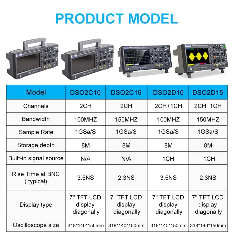
Image: Oscilloscope screen showing two advanced functions: a 3-digit digital voltage meter (DVM) and a 6-digit hardware frequency indicator, along with a serial bus trigger and decode function displaying I2C protocol data.
- Automatic Measurements: Press the MEASURE button to display various waveform parameters automatically (e.g., Vpp, Vmax, Freq, Period).
- Cursor Measurements: Use the CURSOR button to enable cursors for precise manual measurements of voltage and time differences.
- Digital Voltage Meter (DVM): The device includes a DVM function for precise voltage readings.
- Serial Bus Decode: Supports decoding of common serial protocols like I2C, SPI, UART (check specific model capabilities).
- Waveform Storage: Save waveforms and settings to internal memory or a USB drive using the SAVE function.
7. Maintenance
7.1 Cleaning
To maintain the appearance and prolong the life of the instrument, clean the case and front panel regularly. Use a soft cloth dampened with a mild detergent and water. Do not use abrasive cleaners or solvents.
7.2 Calibration
The oscilloscope is factory calibrated. For optimal performance, periodic calibration by qualified personnel is recommended, typically every 1-2 years, depending on usage.
8. Troubleshooting
| Problem | Possible Cause | Solution |
|---|---|---|
| No display after power-on. | Power cord not connected; power switch off; internal fault. | Check power cord connection; ensure power switch is on; contact support if issue persists. |
| No waveform displayed. | Probe not connected; input signal too small/large; trigger settings incorrect; channel off. | Connect probe correctly; adjust Volts/Div; adjust trigger level/mode; ensure channel is enabled. Press AUTO. |
| Waveform is unstable. | Incorrect trigger source or mode; noisy signal. | Adjust trigger source/mode (e.g., Edge, Auto); ensure stable input signal. |
| USB connection issues. | Incorrect cable; driver not installed; software not running. | Use provided USB cable; install necessary drivers on PC; ensure PC software is running. |
9. Specifications
The following table outlines the key technical specifications for the Hantek DSO2D10 Digital Storage Oscilloscope and related models.

Image: A comparison table detailing specifications for Hantek DSO2C10, DSO2C15, DSO2D10, and DSO2D15 models, including channels, bandwidth, sample rate, storage depth, built-in signal source, rise time, display type, and oscilloscope size.
| Parameter | Specification (DSO2D10) |
|---|---|
| Model | DSO2D10 |
| Channels | 2 CH + 1 CH (AWG) |
| Bandwidth | 100 MHz |
| Sample Rate | 1 GSa/s |
| Storage Depth | 8 M |
| Built-in Signal Source | 1 CH (Arbitrary Waveform Generator) |
| Rise Time at BNC (typical) | 3.5 NS |
| Display Type | 7" TFT LCD display diagonally |
| Oscilloscope Size | 318*140*150mm |
| Product Dimensions | 8.66 x 5.91 x 4.72 inches |
| Item Weight | 1.1 Pounds |
| Batteries | 1 Lithium Ion battery required (included) |
10. Warranty and Support
Hantek products are designed for reliability and performance. For warranty information, technical support, or service inquiries, please refer to the warranty card included with your product or visit the official Hantek website. Keep your purchase receipt as proof of purchase.
For further assistance, you may also contact your local distributor or reseller.