
1. Introduction
This manual provides comprehensive instructions for the safe and effective operation of the Hantek DSO8000E Series 6-in-1 Handheld Oscilloscope. This versatile device integrates an oscilloscope, recorder, digital multimeter (DMM), spectrum analyzer, frequency counter, and arbitrary waveform generator (AWG) into a single portable unit. Please read this manual thoroughly before using the instrument to ensure proper functionality and to prevent damage.

Figure 1: Hantek DSO8000E Series Handheld Oscilloscope (Front View). This image displays the front panel of the oscilloscope, showing the screen, control buttons, input ports, and overall ergonomic design.
2. Safety Information
Always observe the following safety precautions to prevent injury and avoid damage to the instrument or connected devices:
- Power Source: Use only the specified power adapter and battery type. Ensure the power supply voltage matches the instrument's requirements.
- Grounding: Ensure proper grounding when connecting to external power sources or circuits.
- Environmental Conditions: Operate the device within the specified temperature and humidity ranges (Operating: 32°F to 122°F (0°C to 50°C); Nonoperating: -40°F to 159.8°F (-40°C to +71°C)). Avoid exposure to direct sunlight, high humidity, dust, or corrosive gases.
- Probe Usage: Use only probes rated for the voltage and current being measured. Do not touch exposed connections or components when power is applied.
- Maintenance: Refer all servicing to qualified personnel. Do not attempt to open or repair the instrument yourself.
- Cleaning: Disconnect power before cleaning. Use a soft, dry cloth. Do not use abrasive cleaners or solvents.
The device is IP-51 rated for dust, drip, and shake proofing, designed to withstand harsh environments. It features a large fuse conforming to European Safety Standards.
3. Product Overview
3.1 Key Features
- Six-in-one functionality: Oscilloscope, Recorder, DMM, Spectrum Analyzer, Frequency Counter, Arbitrary Waveform Generator.
- High bandwidth (70MHz-200MHz) Oscilloscope with 1GSa/s sample rate and 2M Memory depth.
- 25MHz Arbitrary Waveform Generator with 200MSa/s DDS and 12-bit vertical resolution.
- 6000 Counts Digital Multimeter (DMM) for AC/DC voltage, current, resistance, capacitance, and diode/continuity tests.
- FFT spectral analysis, waveform math functions (add, subtract, multiply, divide), X-Y mode, and over 20 automatic measurements.
- PASS/FAIL Check function for engineering applications.
- Abundant trigger functions and double timebase sampling.
- Record and replay of more than 1000 waveforms.
- Large 5.6-inch TFT Color LCD Display with 640x480 resolution.
- USB Host/Device 2.0 full-speed interface; supports removable disk.
- WIFI/LAN Option for PC control (optional).
- Waveform data output in WORD, EXCEL, BMP, JPG formats.
- Battery indicator with easy-changed connect points and selectable 18650 battery box.
- Anti-theft lock hole, tripod fixed hole, hang rope, and built-in flashlight.
- Replaceable BNC safety joints.
3.2 Included Components
The Hantek DSO8000E Series oscilloscope typically includes the following items:
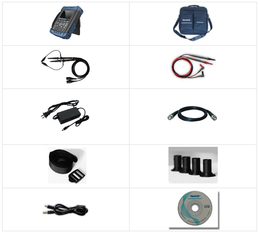
Figure 2: Included Components. This image shows the main unit, carrying bag, oscilloscope probes, multimeter leads, power adapter, BNC cable, shoulder strap, BNC safety joints, USB cable, and software CD.
- Hantek DSO8000E Series Main Unit
- Carrying Bag
- Oscilloscope Probes (x2)
- Multimeter Test Leads
- Power Adapter
- BNC to BNC Cable
- Shoulder Strap
- BNC Safety Joints (additional set)
- USB Cable
- Software CD
- Lithium Ion Battery (pre-installed or included separately)
4. Setup
4.1 Initial Power-Up and Charging
- Battery Installation: If the 18650 Lithium Ion battery is not pre-installed, open the battery compartment and insert the battery, ensuring correct polarity.
- Charging: Connect the power adapter to the instrument's DC input and plug it into a suitable AC outlet. The battery indicator will show charging status. It is recommended to fully charge the battery before first use.
- Power On/Off: Press and hold the power button (usually located on the front panel) to turn the instrument on or off.
4.2 Probe Connection
- Oscilloscope Probes: Connect the BNC connector of the oscilloscope probe to the CH1 or CH2 input on the front panel. Ensure a secure connection.
- Multimeter Leads: For DMM functions, connect the red test lead to the VΩmA input and the black test lead to the COM input. For high current measurements, use the 10A input.
- Probe Compensation: Before making critical measurements, perform probe compensation to ensure accurate readings. Refer to the on-screen menu for the compensation procedure, typically involving connecting the probe to a dedicated compensation signal output.
5. Operating Instructions
The DSO8000E series offers multiple operating modes, accessible via the function buttons on the front panel. The main modes are Oscilloscope, DMM, and Arbitrary Waveform Generator.
5.1 Oscilloscope Mode
This is the primary function for visualizing electrical signals. Use the dedicated 'SCOPE/REC' button to enter this mode.
- Vertical Controls: Use the CH1/CH2 buttons to select channels. Adjust vertical sensitivity (Volts/Div) and position using the corresponding knobs or menu options.
- Horizontal Controls: Adjust the time base (Sec/Div) and horizontal position to view the desired portion of the waveform.
- Trigger System: Configure the trigger type (Edge, Pulse, Video, etc.), source, and level to stabilize the waveform display. The 'AUTOSET' button can automatically adjust settings for a stable display.
- Measurements: Access automatic measurements (e.g., Vpp, Vrms, Frequency, Period) via the 'MEAS' button.
- Waveform Math & FFT: Perform mathematical operations on waveforms (Add, Subtract, Multiply, Divide) or analyze frequency components using the Fast Fourier Transform (FFT) function.
- PASS/FAIL: Set up criteria for waveform comparison to automatically identify signals that fall outside defined limits.
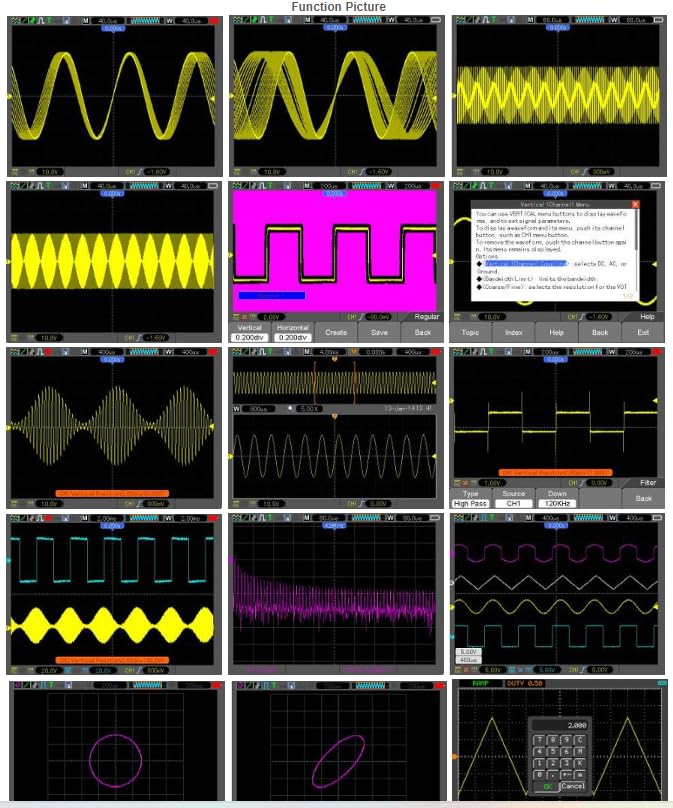
Figure 3: Oscilloscope Function Examples. This image displays various waveform captures and interface elements, demonstrating the device's capability to display sine waves, square waves, modulated signals, and FFT analysis.
5.2 Digital Multimeter (DMM) Mode
The integrated DMM provides precise measurements for various electrical parameters. Use the 'DMM' button to switch to this mode.
- Voltage Measurement: Select AC or DC voltage and connect test leads appropriately.
- Current Measurement: Select AC or DC current. For current measurements, the test leads must be connected in series with the circuit. Use the 10A input for higher currents.
- Resistance, Capacitance, Diode, Continuity: Select the desired function and connect the test leads to the component under test.
5.3 Arbitrary Waveform Generator (AWG) Mode
The AWG allows you to generate various standard and custom waveforms. Use the 'AWG' button to access this mode.
- Waveform Selection: Choose from standard waveforms (sine, square, triangle, pulse) or load custom arbitrary waveforms.
- Parameter Adjustment: Set frequency, amplitude, offset, and duty cycle as required.
- Output: Connect the AWG output to the circuit or device requiring a signal input.
5.4 Recorder, Spectrum Analyzer, and Frequency Counter
These additional functions enhance the utility of the DSO8000E series:
- Recorder: Capture and store long-duration waveform data for later analysis.
- Spectrum Analyzer: Analyze the frequency content of signals using FFT.
- Frequency Counter: Precisely measure the frequency of input signals.
6. Maintenance
6.1 General Care
- Keep the instrument clean and dry. Avoid exposing it to dust, dirt, or liquids.
- Store the device in its carrying bag when not in use to protect it from physical damage.
- Regularly check probes and test leads for damage or wear. Replace them if necessary.
6.2 Battery Maintenance
- Recharge the battery when the low battery indicator appears.
- If the instrument will not be used for an extended period, charge the battery to approximately 50% and store it in a cool, dry place.
- The 18650 battery is user-replaceable. Ensure to use a compatible battery type.
7. Troubleshooting
If you encounter issues with your Hantek DSO8000E Series oscilloscope, refer to the following common troubleshooting steps:
- No Power: Ensure the battery is charged or the power adapter is properly connected. Check the power button.
- No Waveform Display: Verify probes are correctly connected to the input channels and the circuit under test. Check trigger settings (level, source, type). Use 'AUTOSET' to attempt automatic configuration.
- Inaccurate Measurements: Perform probe compensation. Ensure correct probe attenuation settings (1X, 10X, 100X, 1000X) are selected on both the probe and the oscilloscope.
- DMM Readings Incorrect: Check test lead connections and ensure the correct measurement function is selected. Verify the battery charge.
- Device Unresponsive: Try restarting the device. If unresponsive, disconnect power and battery, wait a few minutes, then reconnect and power on.
For persistent issues, contact Hantek customer support.
8. Specifications
8.1 Oscilloscope Mode Specifications

Figure 4: Detailed specifications for the Oscilloscope Mode, including acquisition modes, inputs, impedance, probe attenuation, bandwidth, sample rate, memory depth, vertical resolution, and measurement accuracy for models DSO8072E, DSO8102E, DSO8152E, and DSO8202E.
8.2 DMM Mode Specifications

Figure 5: Detailed specifications for the Digital Multimeter (DMM) Mode, outlining maximum resolution, testing modes, input voltage/current, resistance, capacitance, and diode/continuity test parameters.
8.3 Waveform Generator Mode Specifications
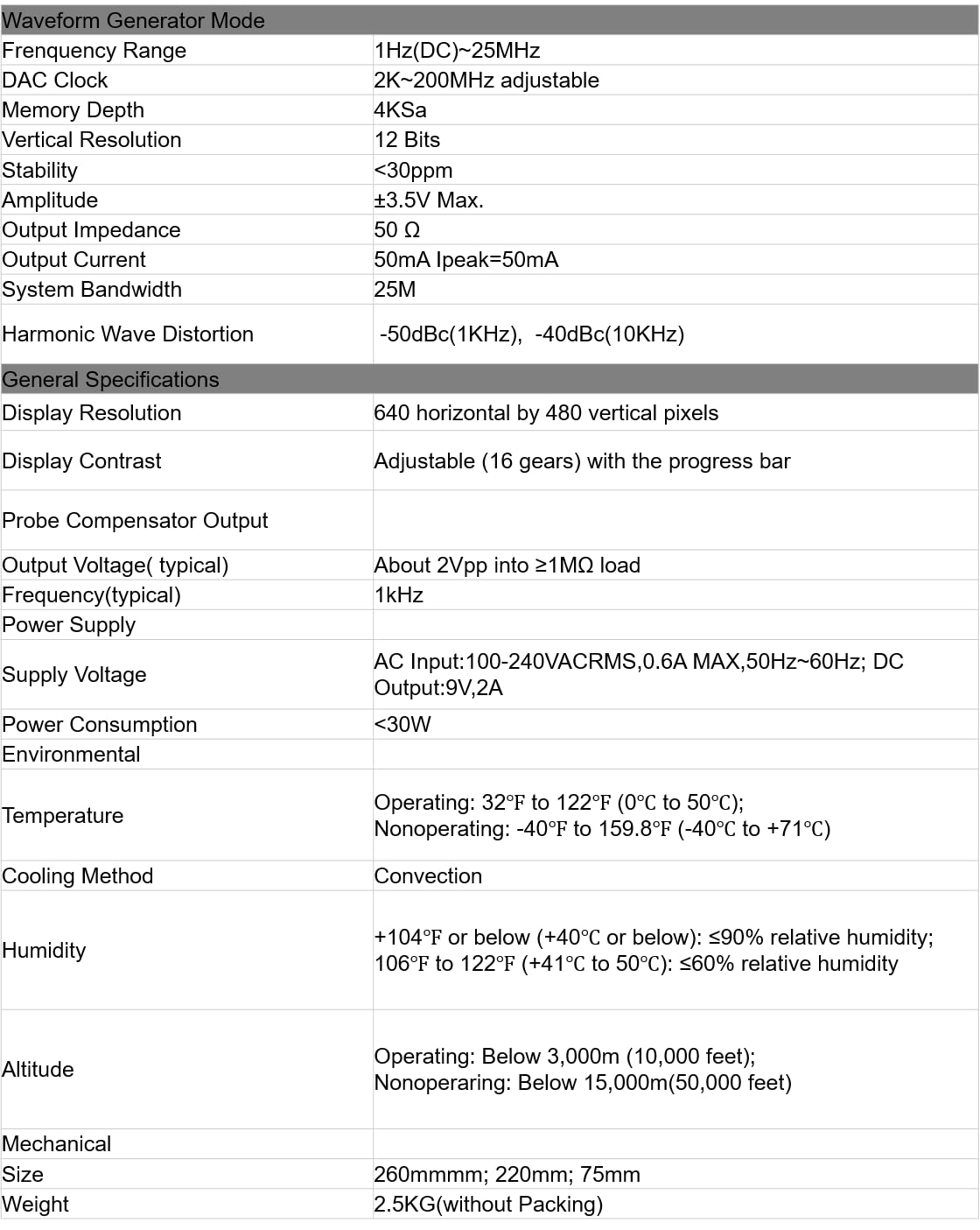
Figure 6: Detailed specifications for the Waveform Generator Mode, including frequency range, DAC clock, memory depth, vertical resolution, stability, amplitude, output impedance, and system bandwidth.
8.4 General Specifications
Figure 7: General specifications for the device, including display resolution, contrast, probe compensator output, power supply, power consumption, environmental conditions (temperature, humidity, altitude), and mechanical dimensions (size, weight).
- Manufacturer: Hantek
- Model Number: GL-DSO8202E (for DSO8202E variant)
- Product Dimensions: 22 x 15 x 12 cm
- Item Weight: 500 g
- Power Source: Battery Powered (1 Lithium Ion battery included)
- Wattage: 5 watts
- Material: Acrylonitrile Butadiene Styrene (ABS)
- Certifications: CE, EMC, ISO 9001, RoHS
- Country of Origin: China
9. Warranty and Support
Hantek products are designed for reliability and performance. For specific warranty details, please refer to the warranty card included with your product or visit the official Hantek website. For technical support, service, or inquiries, please contact Hantek customer service through their official channels.
Manufacturer: Hantek
Website: www.hantek.com (Please verify the official website for your region)