1. Introduction
The LILYGO T-HMI ESP32-S3 is a versatile development board integrating an ESP32-S3 microcontroller with a 2.8-inch ST7789 LCD touch display. It features Wi-Fi and Bluetooth 5.0 connectivity, a TF card slot, and multiple interfaces for various applications. This manual provides essential information for setting up, operating, and maintaining your T-HMI module.
2. Key Features
- Microcontroller: ESP32-S3R8 Dual-core LX7 microprocessor
- Flash Memory: 16MB
- PSRAM: 8MB
- Display: 2.8-inch ST7789 IPS TFT LCD with 240x320 resolution
- Touch Interface: Resistive touch screen with included stylus/pen
- Wireless Connectivity: Wi-Fi and Bluetooth 5 (LE)
- Storage: TF card slot
- Interfaces: Type C USB, 5V DC socket, External Button Backup Interface, Grove connectors
- Onboard Functions: Boot, Reset, Power Button
- Programming Platform Support: Arduino-IDE, MicroPython
3. Product Overview
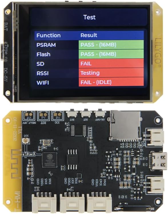
Figure 3.1: Top and bottom view of the LILYGO T-HMI ESP32-S3 development board, showcasing the integrated display and various components.

Figure 3.2: Detailed view of the LILYGO T-HMI ESP32-S3 printed circuit board (PCB), highlighting the ESP32-S3 chip, TF card slot, and various connectors.
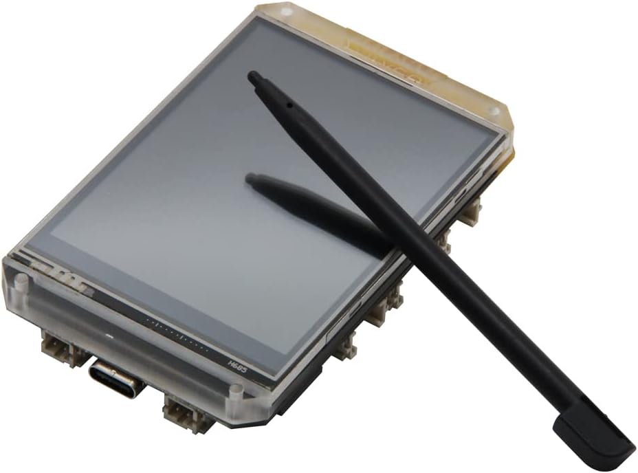
Figure 3.3: The 2.8-inch ST7789 LCD touch display module with the included resistive stylus, used for precise interaction.

Figure 3.4: Comprehensive pinout diagram for the LILYGO T-HMI, detailing connections for the display, TF card, USB, and Grove interfaces.
4. Setup Guide
4.1. Powering the Board
The LILYGO T-HMI can be powered via the Type C USB interface or the 5V DC socket. Connect a compatible 5V power supply to either port. A red charging indicator LED will illuminate when power is supplied.
4.2. TF Card Installation
To utilize the TF card functionality, gently insert a microSD card into the designated TF card slot on the board. Ensure the card is inserted in the correct orientation until it clicks into place.
4.3. Initial Boot-up
Upon connecting power, the board will typically boot up and display a pre-loaded test program on the LCD. This program often checks the functionality of PSRAM, Flash, SD card, RSSI, and WiFi, as shown in Figure 3.1 and 3.3.
4.4. Development Environment Setup
For custom programming, refer to the official LILYGO GitHub repository for the T-HMI module. This resource provides necessary drivers, libraries, and example code for Arduino-IDE and MicroPython development environments.
GitHub Repository: github.com/Xinyuan-LilyGO/T-HMI
5. Operation
5.1. Using the Touch Display
The 2.8-inch ST7789 LCD features a resistive touch screen. Use the provided stylus or a similar pointed, non-sharp object for accurate input. Avoid using excessive force to prevent damage to the screen.
5.2. Onboard Buttons
The board includes several buttons for control:
- Boot Button: Used for entering bootloader mode, typically for flashing new firmware.
- Reset Button: Resets the ESP32-S3 microcontroller, restarting the current program.
- Power Button (ON/OFF): Controls the main power to the board.
5.3. Wireless Connectivity (Wi-Fi & Bluetooth)
The ESP32-S3 supports Wi-Fi and Bluetooth 5.0 (LE) for wireless communication. Functionality will depend on the firmware loaded onto the board. Refer to the development documentation for programming wireless features.
6. Maintenance
To ensure the longevity and optimal performance of your LILYGO T-HMI board, follow these maintenance guidelines:
- Cleaning: Use a soft, dry cloth to clean the display and board. For stubborn smudges on the screen, a slightly damp, lint-free cloth can be used. Avoid abrasive cleaners or solvents.
- Storage: Store the board in a cool, dry environment, away from direct sunlight, extreme temperatures, and high humidity.
- Handling: Handle the board by its edges to avoid touching sensitive components. Static electricity can damage electronic components, so consider using anti-static precautions when handling.
- Power Supply: Always use a stable 5V power supply within the specified current limits.
7. Troubleshooting
If you encounter issues with your LILYGO T-HMI board, consider the following common troubleshooting steps:
7.1. Display Not Lighting Up
- Ensure the power supply is correctly connected and providing 5V.
- Check the Type C USB cable or 5V DC adapter for damage.
- Verify that the board's power switch (if present and used) is in the ON position.
7.2. SD Card Not Detected (FAIL on Test Screen)
- Ensure the TF card is fully inserted into its slot.
- Try a different TF card to rule out card corruption or incompatibility.
- Format the TF card to a compatible file system (e.g., FAT32).
7.3. Wi-Fi/Bluetooth Connectivity Issues (FAIL on Test Screen)
- Ensure the antenna (if external) is properly connected.
- Verify that the firmware loaded on the ESP32-S3 includes the necessary Wi-Fi/Bluetooth drivers and application logic.
- Check for interference from other wireless devices.
7.4. Board Not Responding
- Press the Reset button.
- Disconnect and reconnect the power supply.
- If flashing new firmware, ensure the board is in bootloader mode (often by holding the Boot button while powering on or resetting).
8. Specifications
| Feature | Specification |
|---|---|
| Brand | LILYGO |
| Model | T-HMI ESP32-S3 |
| Microcontroller | ESP32-S3R8 Dual-core LX7 microprocessor |
| Flash Memory | 16 MB |
| PSRAM | 8 MB |
| Display Type | 2.8 inch ST7789 IPS TFT LCD |
| Display Resolution | 240 x 320 pixels |
| LCD Area | 48.6 x 64.8 mm |
| Touch Screen | Resistive |
| Wireless Connectivity | Wi-Fi, Bluetooth 5 (LE) |
| Interfaces | USB Type-C, 5V DC Socket, TF Card Slot, Grove Connectors |
| Power Input | 5V DC |
| Country of Origin | China |

Figure 8.1: Detailed technical specifications and physical dimensions of the LILYGO T-HMI ESP32-S3 module.
9. Support
For further technical support, documentation, and community resources, please visit the official LILYGO GitHub repository and community forums.
Official GitHub: github.com/Xinyuan-LilyGO/T-HMI
For general inquiries or product information, you may visit the LILYGO store on Amazon:
LILYGO Amazon Store: LILYGO Store