1. Introduction
The GVDA GD128PLUS Smart Rechargeable Digital Multimeter is an advanced, versatile tool designed for accurate and reliable electrical measurements. Featuring a 10000-count display, auto-ranging capabilities, and True RMS functionality, it is suitable for professionals and electronics enthusiasts alike. This manual provides essential information for safe and effective operation, setup, maintenance, and troubleshooting of your multimeter.
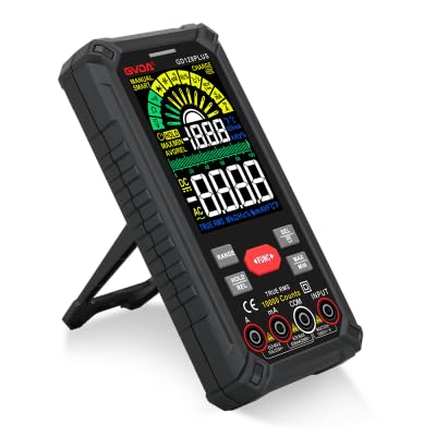
Figure 1.1: GVDA GD128PLUS Digital Multimeter with its integrated kickstand.
2. Safety Information
Always adhere to the following safety precautions to prevent personal injury or damage to the multimeter:
- Do not exceed the maximum input limits for any measurement range.
- Exercise extreme caution when working with voltages above 30V AC RMS, 42V peak, or 60V DC. These voltages pose a shock hazard.
- Always disconnect power to the circuit and discharge all high-voltage capacitors before performing resistance, continuity, or diode tests.
- Ensure the test leads are in good condition, without any damaged insulation.
- Do not operate the multimeter if it appears damaged or if the case is open.
- Use the correct function and range for each measurement.
- Keep fingers behind the finger guards on the test probes during measurements.
- Do not use the multimeter in wet environments or in the presence of explosive gases or dust.
- The Non-Contact Voltage (NCV) function is for indication only; always verify voltage presence with direct measurement.
3. Package Contents
Upon unpacking, verify that all items listed below are present and in good condition:
- 1 x GVDA GD128PLUS Digital Multimeter
- 1 x Pair of Test Leads (Red and Black)
- 1 x USB Charging Cable
- 1 x K-type Thermocouple Probe
- 1 x Cloth Carrying Bag
- 1 x User Manual (this document)
- 1 x Gift Box (packaging)
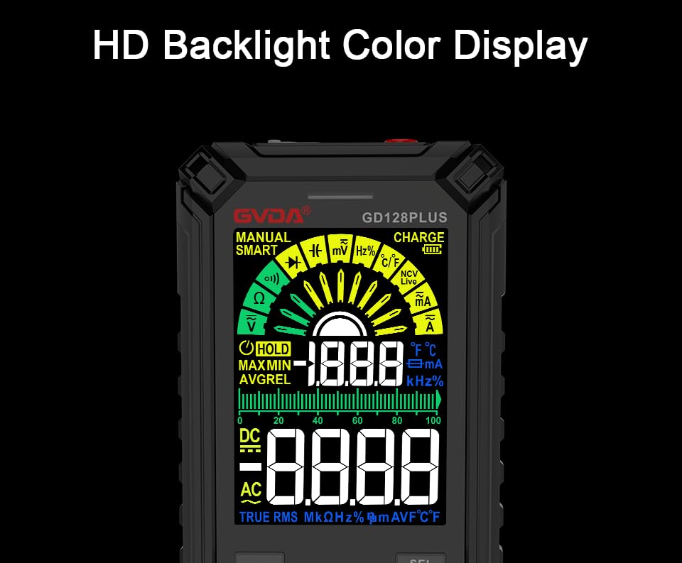
Figure 3.1: All components included in the GVDA GD128PLUS Multimeter package.
4. Product Features and Components
The GD128PLUS multimeter is equipped with a range of features for comprehensive electrical testing:
- 10000 Counts Display: Provides high resolution for precise measurements.
- Auto Range: Automatically selects the appropriate measurement range, simplifying operation.
- True RMS: Ensures accurate readings for non-sinusoidal AC waveforms.
- Rechargeable Lithium Battery: Built-in 3.7V battery for convenience and portability.
- HD Backlight Color Display: Clear and easy-to-read display in various lighting conditions.
- Non-Contact Voltage (NCV) Detection: Safely detects the presence of AC voltage without direct contact.
- LED Flashlight: Integrated light for illuminating dark work areas.
- Data Hold (HOLD): Freezes the current reading on the display.
- Relative Measurement (REL): Displays the difference between a stored reference value and the current reading.
- MAX/MIN Measurement: Records the maximum and minimum values during a measurement session.
- Input Jack LED Indication: Guides correct test lead connection for selected function.
- Overload Protection: Protects the device from damage due to excessive input.
4.1. Multimeter Layout

Figure 4.1: Key components and input jacks of the GVDA GD128PLUS Multimeter.
Refer to Figure 4.1 for the location of the following components:
- Display: HD Backlight Color LCD for readings and indicators.
- Function Buttons: RANGE, HOLD/REL, FUNC, SEL, MAX/MIN.
- Input Jacks:
- COM Jack: Common (negative) input for all measurements.
- VΩHzCap°C/°F Jack: Positive input for Voltage, Resistance, Frequency, Capacitance, and Temperature measurements.
- mAμA Jack: Positive input for milliampere and microampere current measurements.
- 10A Jack: Positive input for 10 Ampere current measurements.
- Power On/Off Button: Located on the top edge.
- Charge Jack: USB-C port for recharging the internal battery.
- Flashlight Key: Button to activate the integrated LED flashlight.
- Warning Indicator: LED light for safety alerts.
- Bracket: Integrated kickstand on the back for hands-free viewing.
5. Setup
5.1. Initial Charging
Before first use, it is recommended to fully charge the multimeter's internal lithium battery. Connect the provided USB charging cable to the multimeter's charge jack and to a standard USB power adapter (not included) or a computer USB port. The display will indicate charging status. A full charge typically takes a few hours.

Figure 5.1: The multimeter's rechargeable lithium battery can be charged directly using a USB cable.
5.2. Attaching Test Leads
For most measurements, connect the black test lead to the COM jack and the red test lead to the appropriate positive input jack (VΩHzCap°C/°F, mAμA, or 10A) depending on the desired measurement function. The input jack LED indicators will illuminate to guide correct connection.
6. Operating Instructions
6.1. Power On/Off
Press and hold the Power On/Off button (located on the top edge) to turn the multimeter on or off. The device features an auto-power-off function to conserve battery life after a period of inactivity.
6.2. Measurement Modes
The GD128PLUS offers various measurement modes, accessible via the rotary dial and function buttons:
6.2.1. Voltage Measurement (AC/DC)
- Turn the rotary dial to the V position. The multimeter will automatically detect AC or DC voltage.
- Connect the black test lead to the COM jack and the red test lead to the VΩHzCap°C/°F jack.
- Connect the test probes in parallel to the circuit or component under test.
- Read the voltage value on the display.
6.2.2. Current Measurement (AC/DC)
- Turn the rotary dial to the mA/μA or 10A position depending on the expected current.
- Connect the black test lead to the COM jack. Connect the red test lead to the mAμA jack for small currents or the 10A jack for larger currents.
- Connect the multimeter in series with the circuit. Ensure the circuit is de-energized before connecting.
- Apply power to the circuit and read the current value.
- Caution: Never connect the multimeter in parallel for current measurement, as this can damage the device and the circuit.
6.2.3. Resistance Measurement (Ω)
- Turn the rotary dial to the Ω position.
- Connect the black test lead to the COM jack and the red test lead to the VΩHzCap°C/°F jack.
- Ensure the circuit is de-energized and all capacitors are discharged before measuring resistance.
- Connect the test probes across the component to be measured.
- Read the resistance value.
6.2.4. Capacitance Measurement (F)
- Turn the rotary dial to the Cap position.
- Connect the black test lead to the COM jack and the red test lead to the VΩHzCap°C/°F jack.
- Ensure the capacitor is fully discharged before connecting the probes.
- Connect the test probes across the capacitor.
- Read the capacitance value.
6.2.5. Frequency Measurement (Hz)
- Turn the rotary dial to the Hz position.
- Connect the black test lead to the COM jack and the red test lead to the VΩHzCap°C/°F jack.
- Connect the test probes in parallel to the signal source.
- Read the frequency value.
6.2.6. Diode Test and Continuity Test
- Turn the rotary dial to the Diode/Continuity position. Use the SEL button to toggle between diode test and continuity test.
- Connect the black test lead to the COM jack and the red test lead to the VΩHzCap°C/°F jack.
- Diode Test: Connect the red probe to the anode and the black probe to the cathode of the diode. A forward voltage drop will be displayed. Reverse the probes; an open circuit (OL) should be displayed.
- Continuity Test: Connect the probes across the circuit or component. A continuous beep indicates a low resistance (continuity).
6.2.7. Non-Contact Voltage (NCV) Detection
- Turn the rotary dial to the NCV position.
- Move the top end of the multimeter near the conductor suspected of having AC voltage.
- The multimeter will emit an audible beep and the warning indicator will flash, with the display showing signal strength, if AC voltage is detected.
- Note: This function is for preliminary detection only. Always use direct contact measurement for precise voltage verification.
6.2.8. Temperature Measurement (°C/°F)
- Turn the rotary dial to the °C/°F position.
- Connect the K-type thermocouple probe to the COM and VΩHzCap°C/°F jacks, observing polarity.
- Place the tip of the thermocouple on or near the object whose temperature is to be measured.
- Read the temperature on the display. Use the SEL button to switch between Celsius and Fahrenheit.
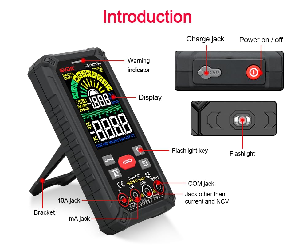
Figure 6.1: The multimeter can perform temperature tests using the included K-type thermocouple probe.
6.3. Special Functions
- RANGE Button: In manual range mode, press to cycle through available ranges. In auto range mode, press to switch to manual range.
- HOLD/REL Button:
- Short press: Activates Data Hold, freezing the current reading. Press again to release.
- Long press: Activates Relative Measurement (REL). The current reading becomes the reference, and subsequent readings show the difference from this reference. Long press again to exit.
- MAX/MIN Button: Press to enter MAX/MIN recording mode. The display will show the maximum, minimum, and average values detected since activation. Press again to cycle through MAX, MIN, AVG. Long press to exit.
- FUNC Button: Used to switch between different functions within the same rotary dial position (e.g., AC/DC voltage, Diode/Continuity).
- Flashlight: Press the dedicated flashlight key on the side to turn the LED flashlight on or off.
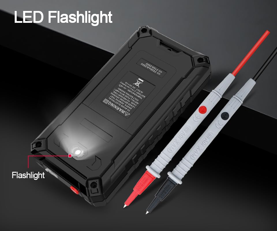
Figure 6.2: The multimeter features a convenient LED flashlight for illuminating work areas.
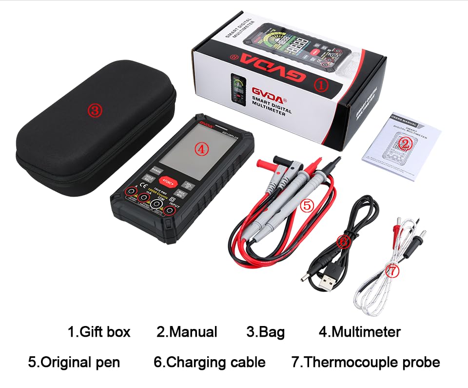
Figure 6.3: The HD Backlight Color Display provides clear and comprehensive measurement information.
7. Maintenance
7.1. Cleaning
Wipe the case with a damp cloth and mild detergent. Do not use abrasives or solvents. Ensure the multimeter is off and disconnected from any circuits before cleaning.
7.2. Battery Charging
The multimeter is equipped with a rechargeable lithium battery. When the low battery indicator appears on the display, connect the multimeter to a USB power source using the provided charging cable. Avoid fully discharging the battery frequently to prolong its lifespan.
7.3. Storage
When not in use for extended periods, store the multimeter in a cool, dry place, away from direct sunlight and extreme temperatures. It is advisable to charge the battery periodically (e.g., every 3-6 months) to maintain its health.
8. Troubleshooting
| Problem | Possible Cause | Solution |
|---|---|---|
| Multimeter does not power on. | Low or depleted battery. | Charge the multimeter using the USB cable. |
| "OL" (Overload) displayed. | Measurement exceeds selected range or meter's maximum capacity. | Switch to a higher range (if in manual range) or ensure the measurement is within the meter's specifications. |
| Inaccurate readings. | Incorrect function/range selected; poor test lead connection; external interference. | Verify function and range; ensure test leads are securely connected; move away from strong electromagnetic fields. |
| No continuity beep. | Circuit is open; multimeter not in continuity mode. | Check the circuit for breaks; ensure the multimeter is set to continuity mode (use SEL button if necessary). |
9. Specifications
| Parameter | Value |
|---|---|
| Display | 10000 Counts, HD Backlight Color LCD |
| Ranging | Auto/Manual Range |
| True RMS | Yes |
| DC Voltage Range | Up to 1000V |
| AC Voltage Range | Up to 750V |
| DC Current Range | Up to 10A |
| AC Current Range | Up to 10A |
| Resistance Range | Yes (Ohm) |
| Capacitance Range | Yes (Farad) |
| Frequency Range | Yes (Hz) |
| Temperature Range | -40°C to 1000°C / -40°F to 1832°F |
| Diode Test | Yes |
| Continuity Test | Yes (with buzzer) |
| NCV (Non-Contact Voltage) | Yes |
| Power Supply | 3.7V Rechargeable Lithium Battery |
| Sampling Rate | Approx. 3 times per second |
| Dimensions | 166mm x 83mm x 29mm (approx. 6.5 x 3.3 x 1.1 inches) |
| Weight | Approx. 1.26 Pounds (0.57 kg) |
| Operating Environment | 0-40°C, relative humidity <80% |
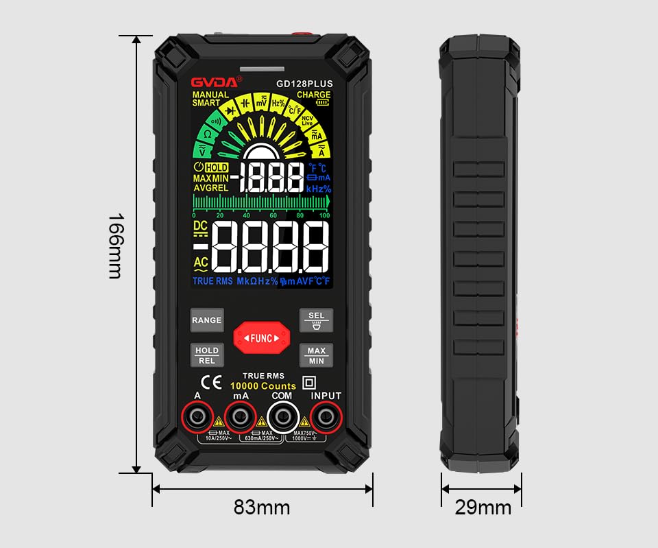
Figure 9.1: Physical dimensions of the GVDA GD128PLUS Multimeter.
10. Warranty and Support
This GVDA GD128PLUS Digital Multimeter is designed for reliability and performance. For warranty information, technical support, or service inquiries, please refer to the contact details provided by your retailer or visit the official GVDA website. Please retain your proof of purchase for warranty claims.


