
1. Introduction
The PandaRC VT5804HV MAX is a high-performance 5.8GHz FPV Video Transmitter (VTX) designed for FPV racing drones. It offers switchable output power levels from 0mW (PIT mode) up to 1000mW, ensuring stable video transmission over various distances. This manual provides essential information for the proper installation, operation, and maintenance of your VT5804HV MAX VTX.
2. Product Features
- Adjustable Output Power: Supports 0mW (PIT), 25mW, 200mW, 400mW, 800mW, and 1000mW switchable power levels for versatile use.
- High-Efficiency Heat Sink: Integrated design for effective heat dissipation, ensuring stable performance.
- IRC Tramp Protocol Support: Allows modification of VTX parameters directly through remote control via OSD configuration.
- Protective Shield: Includes an optional protective shield to safeguard the transmitter during impacts.
- PIT Mode: Enables safe testing and adjustments without interfering with other pilots' frequencies.
- Fast Frequency Locking: Ensures quick startup without causing interference to other users.
- Self-Checking Function: Provides a quick method to verify normal VTX operation.
- Built-in Microphone: For audio transmission.
- Removable Mounting Hole: Offers flexible installation options.
3. Technical Specifications
| Parameter | Value |
|---|---|
| Product Model | VT5804HV MAX |
| Input Voltage | 6-36V |
| Output Power | 0mW/25mW/200mW/400mW/800mW/1000mW |
| Antenna Interface | MMCX |
| Working Current | 9V/700mA@1W |
| Weight | ≤8g |
| Number of Channels | 40CH (A-B-E-F-R) |
| Mounting Hole Size | 30.5mm x 30.5mm |
| Dimensions | 36mm x 36mm x 4.2mm |
| Video Format | NTSC/PAL auto |
| Parameter Adjustment Method | Button/OSD |
Note: Specifications are subject to change without prior notice.

Image: Detailed product parameters for the VT5804HV MAX VTX.
4. Package Contents
Upon opening the package, ensure all the following items are present:
- 1 x PandaRC VT5804HV MAX 5.8GHz FPV Video Transmitter
- 1 x Antenna
- 1 x Wiring Harness

Image: The PandaRC VT5804HV MAX VTX, antenna, wiring harness, and a user manual snippet showing interface definitions.
5. Safety Information
- Always keep the VTX away from heat sources to prevent damage or malfunction.
- Ensure correct polarity when connecting power to avoid irreversible damage to the unit.
- Do not operate the VTX without an antenna connected, as this can damage the transmitter.
- Always verify local regulations regarding FPV transmission power and frequencies before operation.
- Recommended age for use is 14 years and up.
6. Product Overview and Dimensions
Familiarize yourself with the components and physical dimensions of the VT5804HV MAX VTX.
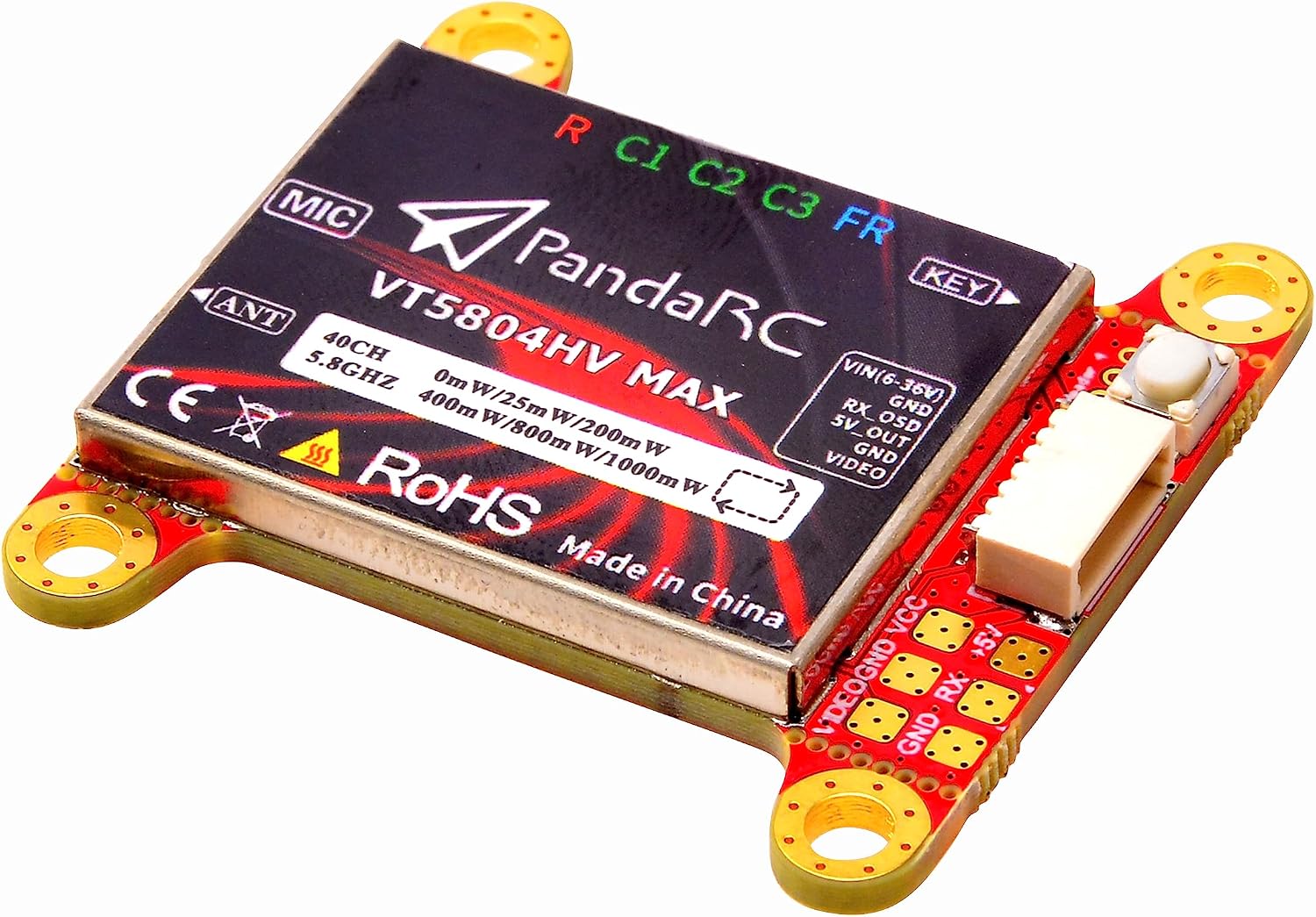
Image: Top view of the PandaRC VT5804HV MAX VTX module, showing the heat sink and labels.
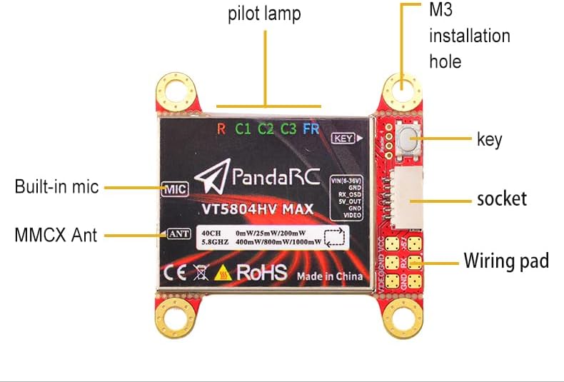
Image: Labeled diagram identifying key components such as the built-in mic, MMCX antenna connector, pilot lamp, key button, socket, wiring pad, and M3 installation holes.
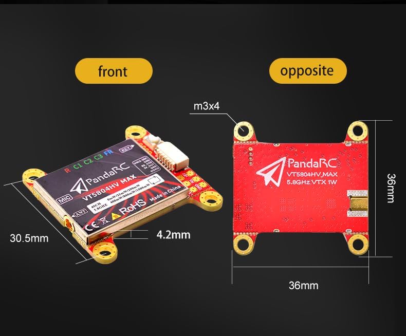
Image: Front and opposite views of the VT5804HV MAX, illustrating its dimensions (36mm x 36mm x 4.2mm) and M3 mounting hole pattern.
7. Setup and Installation
7.1 Wiring Diagram
Refer to the following pin definitions for proper connection to your flight controller or power distribution board:
| Pin Name (6-PIN) | Description |
|---|---|
| Video | Video signal input (PAL/NTSC) |
| GND | Ground |
| VCC | Power supply VCC input (6-36V) |
| GND | Ground |
| 5V OUT | Power supply 5V output |
| RX | Smart Audio / Connect to flight control TX (for OSD control) |
For the 4-PIN interface, the pins are typically GND, RX, and Video, with an additional VCC if separate power is used.
7.2 Mounting
The VT5804HV MAX features a 30.5mm x 30.5mm mounting pattern, compatible with most standard flight controller stacks. Use M3 screws for secure installation.
7.3 Antenna Connection
Connect the provided MMCX antenna to the MMCX connector on the VTX. Ensure the connection is firm. Never power on the VTX without an antenna connected.
8. Operating Instructions
8.1 Power On
Once correctly wired and an antenna is attached, apply power within the 6-36V range. The VTX will power on and indicate its current status via LEDs.
8.2 Channel, Band, and Power Adjustment
The VT5804HV MAX supports two primary methods for adjusting settings:
- OSD Configuration (IRC Tramp Protocol): Connect the VTX's RX pin to a TX pad on your flight controller and configure Smart Audio in your flight controller software (e.g., Betaflight). This allows for convenient adjustment of channel, band, and power settings directly from your FPV goggles or remote control OSD.
- Button Control: The VTX features a physical button for manual adjustments.
LED Indicators: The VTX uses a series of LEDs to indicate the current frequency band, channel, and power level.

Image: Frequency table showing channel frequencies for bands A, B, E, F, R, and LED indicators for power levels (25mW, 200mW, 400mW, 800mW, 1W).
Refer to the diagram above for interpreting the LED patterns for frequency and power settings. Typically, short presses cycle through channels, long presses cycle through bands, and very long presses cycle through power levels.
8.3 PIT Mode
PIT Mode (0mW) allows the VTX to be powered on without transmitting a strong signal, preventing interference with other pilots. This is ideal for making adjustments or repairs at an FPV event. Activate PIT mode via OSD or button control as per the LED indicator guide.
9. Troubleshooting
- No Video Signal:
- Check all wiring connections, especially Video IN and GND.
- Ensure the VTX is powered on and receiving adequate voltage.
- Verify that your FPV goggles/receiver are on the correct frequency and band.
- Confirm the antenna is securely attached to both the VTX and receiver.
- Poor Video Quality/Short Range:
- Increase the VTX output power if operating at a low setting.
- Check for obstructions between the drone and receiver.
- Inspect antennas for damage or loose connections.
- Ensure there is no significant interference from other electronic components on the drone.
- VTX Overheating:
- Ensure adequate airflow around the VTX.
- Avoid operating at maximum power for extended periods in enclosed spaces without cooling.
- Verify input voltage is within the specified range (6-36V).
- Settings Not Changing via OSD:
- Confirm the RX pin is correctly connected to the flight controller's TX pad.
- Verify Smart Audio (or similar protocol) is enabled and configured correctly in your flight controller software.
- Check for firmware compatibility issues.
- Self-Checking Function: The VTX supports a self-checking function to quickly diagnose operational status. Consult the full PandaRC user manual (if available) for specific instructions on activating and interpreting the self-check results.
10. Instructional Videos
The following videos provide additional visual guidance for the product.
Video 1: Product Overview
Description: This video provides a brief overview of the PandaRC VT5804HV MAX VTX, highlighting its key features and design. (Duration: 0:21)
Video 2: Basic Functionality Demonstration
Description: A short demonstration showcasing some basic functionalities or aspects of the VT5804HV MAX VTX. (Duration: 0:45)
11. Warranty and Support
GEPAS, as the manufacturer, stands behind the quality of the PandaRC VT5804HV MAX. For any questions, technical assistance, or warranty claims, please contact your retailer or the manufacturer's customer support. Please retain your proof of purchase for warranty purposes.