
HFCCYBGS SM8126A
Contents
Battery Internal Resistance Meter Tester and Voltage Measurement Instrument
Model: SM8126A
Brand: HFCCYBGS
1. Introduction
The HFCCYBGS SM8126A is a precision instrument designed for measuring the internal resistance and voltage of batteries. It utilizes a 1kHz sine wave for internal resistance measurement and incorporates an infrared probe for monitoring battery temperature, providing a comprehensive evaluation of battery status.
Key features include:
- Kelvin four-wire test clamp for accurate and secure connections.
- High resolution for internal resistance measurements (down to 0.01mΩ).
- Portable operation with rechargeable lithium battery power supply.
- Optional infrared temperature probe for battery temperature monitoring.
This manual provides essential information for the safe and effective operation, maintenance, and troubleshooting of your SM8126A instrument. Please read it thoroughly before use.
2. Product Overview and Components
The SM8126A instrument comes with the main unit and essential accessories to facilitate accurate measurements.
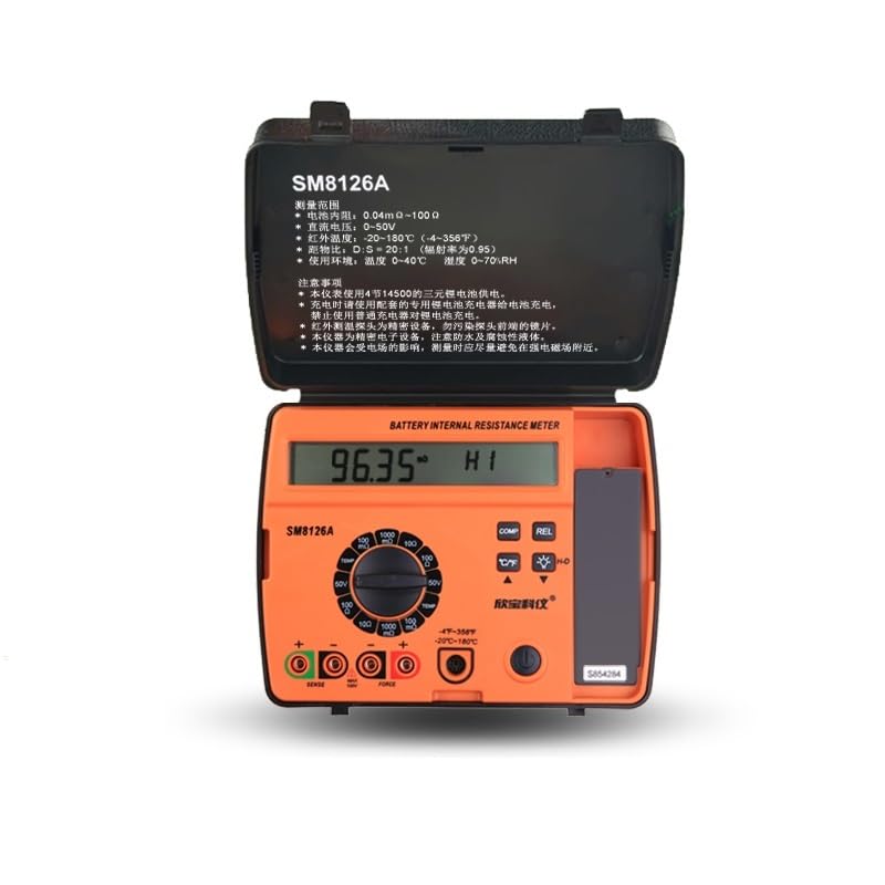
Figure 2.1: The SM8126A Battery Internal Resistance Meter Tester with its protective case open, displaying the main unit and its controls.
The standard package includes:
- SM8126A Host Unit
- Kelvin Four-Wire Test Clamps (clip-style)
- Infrared Temperature Sensor (optional, but mentioned in description)
- Rechargeable Lithium Batteries (14500 3.7V x 4)
- Charging Cable/Adapter (implied for rechargeable batteries)
- Protective Carrying Case
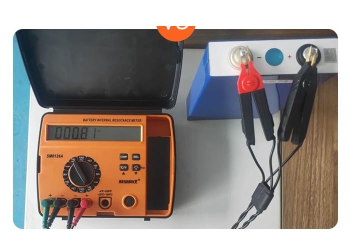
Figure 2.2: The SM8126A instrument securely stored within its protective carrying case.
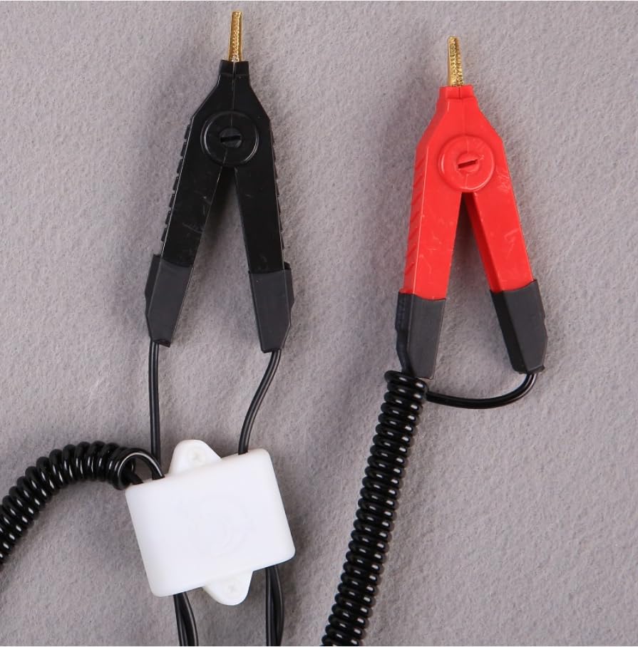
Figure 2.3: Detailed view of the Kelvin four-wire test clamps, showing the separate sense and force connections for accurate measurement.
3. Setup
3.1 Battery Installation and Charging
The SM8126A is powered by four 14500 3.7V ternary lithium-ion rechargeable batteries. Ensure batteries are correctly inserted according to polarity markings inside the battery compartment. For initial use or after prolonged storage, fully charge the batteries using the provided charger.
3.2 Connecting Test Leads and Probes
The instrument uses Kelvin four-wire test clamps for precise measurements. Connect the red and black 'FORCE' leads to the corresponding 'FORCE' terminals on the instrument, and the green and yellow 'SENSE' leads to the 'SENSE' terminals. Ensure a secure connection.
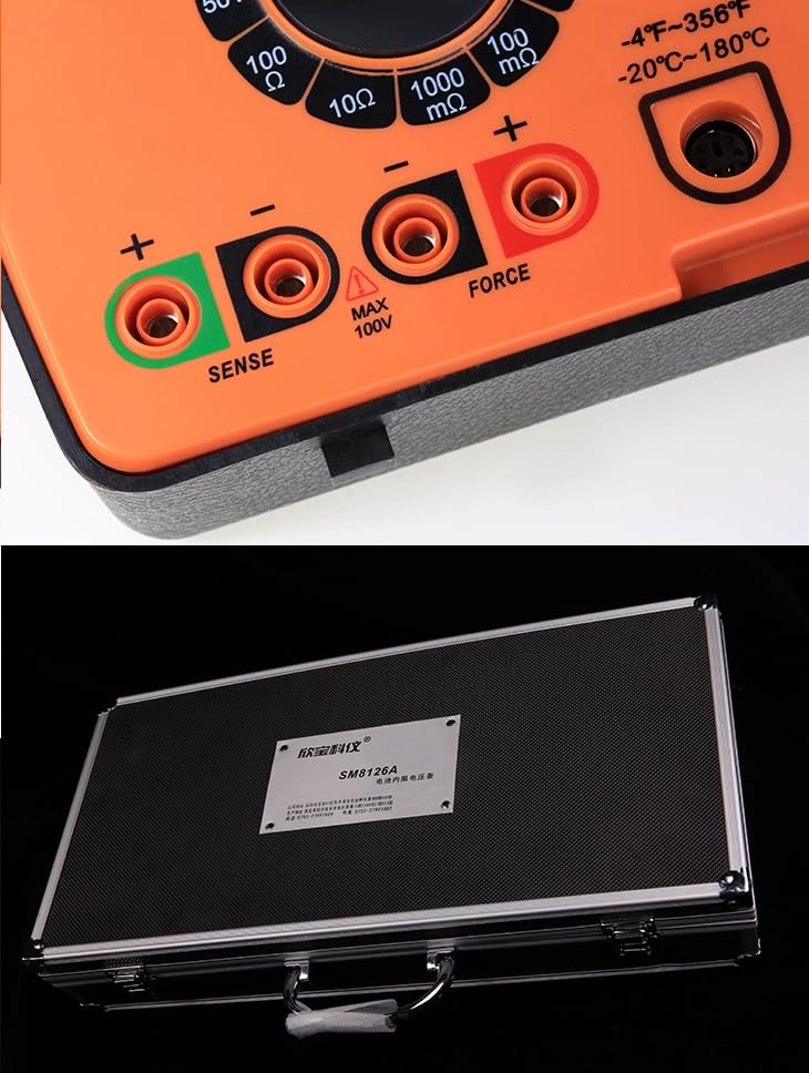
Figure 3.1: Close-up view of the input jacks on the SM8126A, showing the 'SENSE' and 'FORCE' terminals for test lead connection.
If using the optional infrared temperature probe, connect it to the designated temperature input port on the instrument.
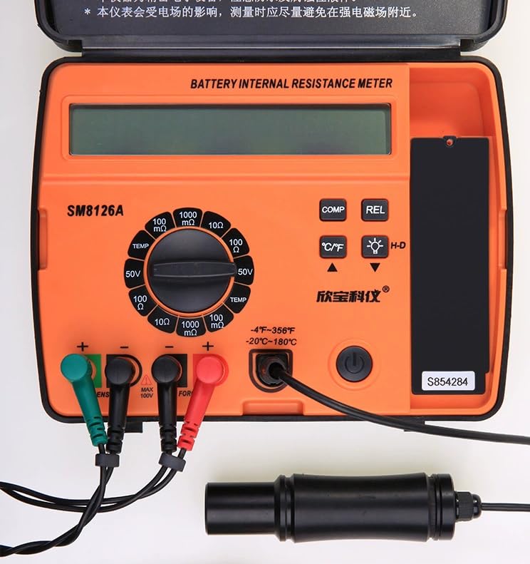
Figure 3.2: The SM8126A instrument with the Kelvin four-wire test leads and the infrared temperature probe connected, ready for operation.
4. Operating Instructions
4.1 Powering On/Off
Press and hold the power button (usually marked with a circle and a vertical line) to turn the instrument on or off. The LCD display will illuminate upon power-on.
4.2 Selecting Measurement Mode
Rotate the central rotary switch to select the desired measurement range for internal resistance (e.g., 100mΩ, 1000mΩ, 10Ω, 100Ω), voltage (50V), or temperature (TEMP). The selected mode and range will be indicated on the display.
4.3 Performing Measurements
- Internal Resistance & Voltage:
- Ensure the Kelvin four-wire test clamps are securely connected to the instrument.
- Carefully attach the test clamps to the terminals of the battery to be tested. Ensure good contact. The red clamp typically connects to the positive terminal, and the black clamp to the negative terminal.
- The instrument will display the internal resistance and voltage readings simultaneously or sequentially, depending on the selected mode.
- Temperature Measurement (with optional probe):
- Point the infrared temperature probe towards the surface of the battery whose temperature you wish to measure.
- Ensure the distance-to-spot ratio (D:S) is considered for accurate readings (D:S = 20:1 for this instrument).
- The temperature reading will be displayed on the screen. Use the °C/°F button to switch between Celsius and Fahrenheit.
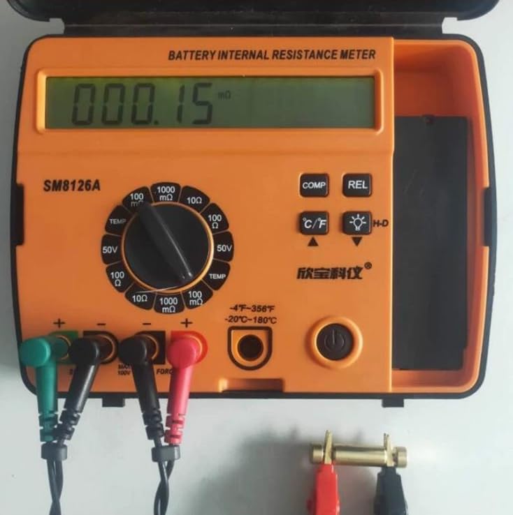
Figure 4.1: The SM8126A display showing a typical measurement reading, indicating the measured value and units.
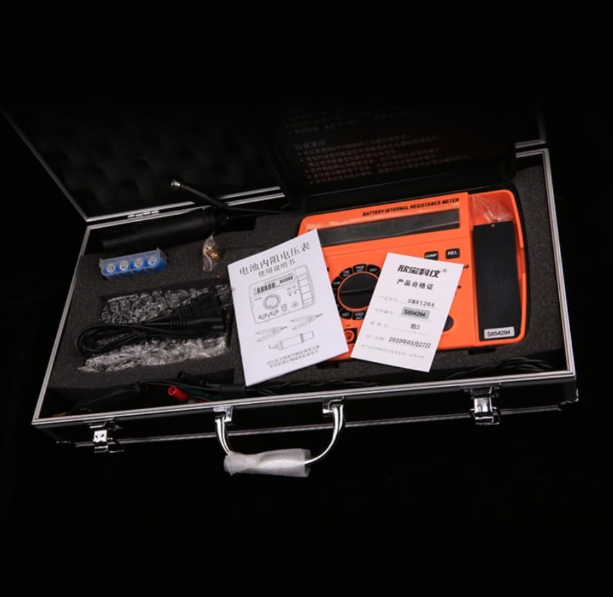
Figure 4.2: The SM8126A instrument actively measuring the internal resistance and voltage of a battery using the connected Kelvin clamps.
4.4 Understanding Display Indicators
The LCD display provides numerical readings and various indicators:
- Numerical Value: The primary measurement result.
- Units: mΩ, Ω for resistance; V for voltage; °C, °F for temperature.
- Battery Indicator: Shows the remaining battery life. Recharge when low.
- "HI" / "LO" (or similar): May indicate readings outside the selected range or comparison results.
5. Maintenance
5.1 Cleaning
Wipe the instrument's exterior with a soft, dry cloth. For stubborn dirt, a slightly damp cloth with mild detergent can be used, ensuring no liquid enters the device. Do not use abrasive cleaners or solvents.
5.2 Battery Care
Recharge the internal lithium-ion batteries regularly to maintain optimal performance. If the instrument will not be used for an extended period, it is recommended to charge the batteries to approximately 50% and store the device in a cool, dry place. Avoid fully discharging the batteries for long periods.
5.3 Storage
Store the SM8126A in its protective carrying case when not in use to prevent damage from dust, moisture, and impact. Keep it away from direct sunlight and extreme temperatures.
6. Troubleshooting
This section addresses common issues you might encounter with the SM8126A instrument.
| Problem | Possible Cause | Solution |
|---|---|---|
| Instrument does not power on. | Low or depleted batteries. Incorrect battery installation. | Charge the batteries. Check battery polarity and ensure they are properly seated. |
| Inaccurate or unstable readings. | Poor contact with battery terminals. Incorrect measurement range selected. Damaged test leads. | Ensure test clamps make firm, clean contact. Select an appropriate measurement range. Inspect test leads for damage and replace if necessary. |
| Temperature probe not working. | Probe not securely connected. Probe malfunction. | Verify the temperature probe is fully inserted into its port. If issue persists, the probe may require replacement. |
| Display shows "OL" or "OVER". | Measurement value exceeds the selected range. | Switch to a higher measurement range. |
7. Specifications
The following table details the technical specifications of the SM8126A Battery Internal Resistance Meter Tester.
| Parameter | Value |
|---|---|
| Internal Resistance Measurement Range | 0.04mΩ – 100Ω |
| Internal Resistance Resolution | 0.01mΩ (100mΩ range), 0.1mΩ (1000mΩ range), 0.001Ω (10Ω range), 0.01Ω (100Ω range) |
| Internal Resistance Maximum Error | ±(4% + 2 words) (valid from 0.1% of full scale) |
| Voltage Measurement Range | 0.00V – 50V |
| Voltage Resolution | 0.01V |
| Voltage Maximum Error | ±(2% + 1 word) |
| Temperature Measurement Range | -20.0°C – 180.0°C (-4°F – 356°F) |
| Temperature Resolution | 0.5°C (1.0°F) |
| Temperature Maximum Error | ±(2% + 1 word) |
| Infrared Temperature D:S Ratio | 20:1 |
| Operating Environment Temperature | 0°C – 40°C |
| Operating Environment Humidity | ≤ 70%RH |
| Power Supply | 4 x 14500 3.7V Ternary Lithium-ion Rechargeable Batteries |
| Weight (without batteries) | 530g (1.17 Pounds) |
| Dimensions (L×W×H) | 210 × 160 × 60 mm |
8. Warranty and Support
For warranty information and technical support, please refer to the documentation provided with your purchase or contact the manufacturer directly. Keep your proof of purchase for any warranty claims.
Manufacturer: HFCC
Model Number: SM8126A
UPC: 717023669311
Documents and downloads
Ask a question about this manual
Ask about setup, troubleshooting, compatibility, parts, safety, or missing instructions. Manuals+ will review the question and use this page’s manual context to help answer it.