
1. Introduction
Thank you for choosing the KONGTEN VICTOR 923D/923E Smart Digital Multimeter. This device is designed for safe and accurate measurement of various electrical parameters. It features automatic identification, a large screen, and a burn-proof design, making it suitable for both professional and home use. Please read this manual thoroughly before use to ensure proper operation and safety.
2. Safety Information
Always observe safety precautions when using this multimeter. Failure to do so may result in electric shock, injury, or damage to the meter or equipment under test.
- Do not exceed the maximum input values specified for each range.
- Ensure test leads are properly connected and in good condition before each use.
- Do not use the meter if it appears damaged or if the casing is open.
- Exercise extreme caution when working with voltages above 60V DC or 30V AC RMS.
- Always disconnect power to the circuit and discharge high-voltage capacitors before measuring resistance, continuity, diodes, or capacitance.
- Replace batteries promptly when the low battery indicator appears.
- Adhere to local and national safety codes.
3. Product Overview
The VICTOR 923D and 923E are smart digital multimeters designed for ease of use and reliability. They feature a large display and intuitive controls.

Figure 3.1: Overview of the VICTOR 923D and 923E Smart Digital Multimeters. The 923D (right) features a black and white TN display, while the 923E (left) has a color VA display.
3.1 Key Components
- Large LCD Display: Shows measurement readings, units, and function indicators. The 923E model features a color VA display for enhanced visibility.
- Function Buttons:
- Power Button: Turns the multimeter on/off.
- SEL Button: Selects between different measurement modes within a function (e.g., AC/DC, Diode/Continuity).
- HOLD Button: Freezes the current display reading.
- FUNC Button: Cycles through various functions (e.g., Hz%, °C/°F, NCV/Live).
- Input Jacks:
- COM Jack: Common terminal for all measurements.
- INPUT Jack: Positive input for voltage, resistance, capacitance, frequency, diode, continuity, and temperature measurements.
- A Jack: Positive input for current measurements up to 10A.
- mA Jack: Positive input for current measurements up to 600mA.
- NCV Sensor: Non-Contact Voltage detection.
- Flashlight: For illuminating dark work areas.
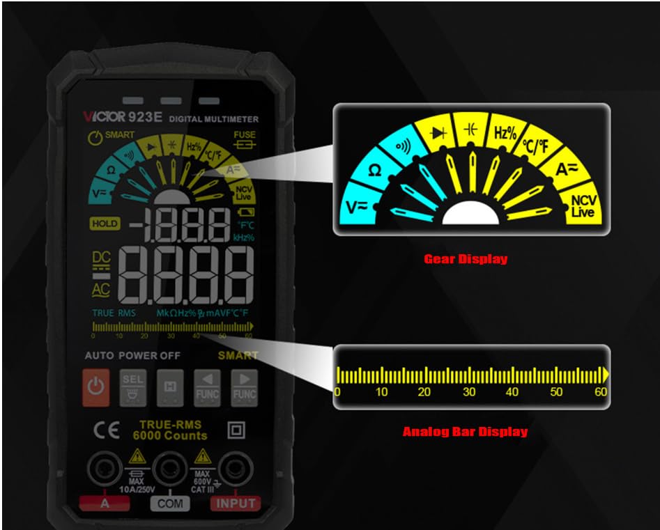
Figure 3.2: Detailed view of the 923E display, illustrating the Gear Display for function indication and the Analog Bar Display for trend visualization.
4. Setup
4.1 Battery Installation
The multimeter requires two 1.5V AAA batteries for operation. The battery compartment is located on the back of the device.
- Ensure the multimeter is powered off.
- Locate the battery compartment cover on the rear of the device.
- Use a screwdriver to open the battery compartment.
- Insert two 1.5V AAA batteries, observing the correct polarity (+ and -).
- Replace the battery compartment cover and secure it with the screw.
4.2 Connecting Test Leads
Always connect the black test lead to the COM jack. Connect the red test lead to the appropriate input jack based on the measurement type:
- For Voltage, Resistance, Capacitance, Frequency, Diode, Continuity, and Temperature: Connect the red lead to the INPUT jack.
- For Current (up to 10A): Connect the red lead to the A jack.
- For Current (up to 600mA): Connect the red lead to the mA jack.
5. Operation
The VICTOR 923D/923E features an intelligent automatic identification mode for common measurements, simplifying operation.

Figure 5.1: The VICTOR 923D Multimeter display, showing indicators for DC/AC Voltage and Current measurements.
5.1 Power On/Off
Press the Power button to turn the multimeter on. Press and hold the Power button to turn it off. The meter also features an Auto Power Off function to conserve battery life.
5.2 Automatic Identification (SMART) Mode
In SMART mode, the multimeter automatically recognizes and measures voltage, resistance, and continuity. Simply connect the test leads to the circuit, and the meter will display the appropriate reading.
5.3 Manual Function Selection
For specific measurements or to override SMART mode, use the SEL and FUNC buttons.
- Voltage Measurement (DC/AC):
- Connect the red lead to the INPUT jack and the black lead to COM.
- Press SEL to cycle between DC and AC voltage if not automatically detected.
- Connect the test leads in parallel to the circuit or component.
- Current Measurement (DC/AC):
- Connect the red lead to the A (for up to 10A) or mA (for up to 600mA) jack, and the black lead to COM.
- Press SEL to cycle between DC and AC current.
- Connect the test leads in series with the circuit.
- CAUTION: Never connect the meter in parallel to a voltage source when measuring current, as this can blow the fuse or damage the meter.
- Resistance Measurement:
- Connect the red lead to the INPUT jack and the black lead to COM.
- Ensure the circuit is de-energized.
- Connect the test leads across the component to measure resistance.
- Capacitance Measurement:
- Connect the red lead to the INPUT jack and the black lead to COM.
- Ensure the capacitor is fully discharged before connecting the leads.
- Connect the test leads across the capacitor.
- Frequency (Hz%) Measurement:
- Connect the red lead to the INPUT jack and the black lead to COM.
- Connect the test leads to the signal source.
- Temperature Measurement (°C/°F):
- Connect the temperature probe (if included) to the INPUT and COM jacks.
- Press FUNC to select temperature mode. Press SEL to switch between Celsius and Fahrenheit.
- Place the probe tip on the object to be measured.
- Diode Test / Continuity Test:
- Connect the red lead to the INPUT jack and the black lead to COM.
- Press SEL to cycle between Diode and Continuity modes.
- For Diode Test: Connect leads across the diode. A forward bias voltage drop will be displayed.
- For Continuity Test: Connect leads across the circuit. An audible beep indicates continuity (low resistance).
- Non-Contact Voltage (NCV) Detection:
- Press FUNC to select NCV mode.
- Move the top of the multimeter near a live conductor. The meter will beep and the NCV indicator will light up if AC voltage is detected.
- LIVE Wire Detection:
- Press FUNC to select LIVE mode.
- Insert the red test lead into the live wire socket or touch the live wire. The meter will indicate if it's a live wire.
5.4 Special Functions
- Data Hold (HOLD): Press the HOLD button to freeze the current reading on the display. Press again to release.
- Flashlight: Press the FUNC button briefly to turn on/off the flashlight.
6. Maintenance
6.1 Cleaning
Wipe the case with a damp cloth and mild detergent. Do not use abrasives or solvents. Keep the input terminals free of dirt and moisture.
6.2 Battery Replacement
When the low battery indicator appears on the display, replace the batteries as described in Section 4.1. Ensure the meter is off before opening the battery compartment.
6.3 Fuse Replacement
If the current measurement function fails, the fuse may need replacement. Refer to the specifications for the correct fuse type. Fuse replacement should only be performed by qualified personnel.
- Ensure the multimeter is powered off and test leads are disconnected.
- Open the back casing of the multimeter (this may require removing multiple screws beyond the battery compartment).
- Locate the blown fuse and carefully remove it.
- Replace with a fuse of the identical type and rating (e.g., FUSE 10A/250V for the 10A range, FUSE 600mA/250V for the mA range).
- Securely close the casing.
7. Troubleshooting
- Meter does not power on: Check battery installation and ensure batteries are fresh.
- No reading or "OL" displayed:
- Ensure test leads are properly connected to the correct input jacks.
- Verify the circuit is complete and the component is not open.
- Check if the measurement range is exceeded (meter should auto-range, but manual selection might be needed for specific cases).
- Inaccurate readings:
- Check battery level.
- Ensure test leads are making good contact.
- Verify the correct measurement function is selected.
- Ensure the circuit is de-energized for resistance, continuity, and capacitance measurements.
- Current measurement not working: Check the fuse for the current input jack.
8. Specifications
The following table outlines the general and measurement specifications for the VICTOR 923D and 923E multimeters.

Figure 8.1: Comprehensive measurement ranges and accuracy for VICTOR 923D and 923E models.
| Measurement | Range (923D/923E) | Accuracy (923D/923E) |
|---|---|---|
| DC Voltage | 600mV/6V/60V/600V | ±(0.5%+3) |
| AC Voltage | 6V/60V/600V | ±(0.8%+3) |
| DC Current | 600mA/10A | ±(1.2%+3) |
| AC Current | 600mA/10A | ±(1.2%+3) |
| Resistance | 600Ω/6kΩ/60kΩ/600kΩ/6MΩ/60MΩ | ±(1.0%+5) |
| Capacitance | 6nF/60nF/600nF/6uF/60uF/6mF | ±(4.0%+5) |
| Frequency | 60Hz/600Hz/6kHz/60kHz/6MHz/10MHz | ±(1.0%+3) |
| Temperature | -40°C~1000°C / -40°F~1832°F | ±2% or ±4°F |
| Duty Cycle | 1.0~99.0% | ±(1.0%+3) |
General Specifications
- Display: 6000 Counts (923D: TN Black and White, 923E: VA Color Display)
- True RMS: Yes
- Diode / Continuity Test: Yes
- NCV (Non-Contact Voltage) Detection: Yes
- Flashlight Function: Yes
- Data Hold: Yes
- Auto Power Off: Yes
- Overload Protection: Yes
- Power Source: 2 x 1.5V AAA Batteries (included)
- Product Dimensions: 146 x 73 x 26 mm
- Product Weight: 182g
- Operating Temperature: 0°C to 50°C (32°F to 122°F)
- Safety Rating: CAT III 600V
- Certifications: CE, FCC, ISO 9001, RoHS
9. Warranty & Support
KONGTEN provides a standard manufacturer's warranty for this product. For detailed warranty terms, technical support, or service inquiries, please refer to the contact information provided with your purchase or visit the official KONGTEN website.
Please retain your proof of purchase for warranty claims.