1. Introduction and Overview
The OSEVEN DSO-TC3 is a versatile, compact, and portable multi-functional instrument designed for electronics enthusiasts, DIYers, and professionals. It integrates a digital oscilloscope, a transistor tester, and a function signal generator into a single device, making it an indispensable tool for various electronic testing and debugging tasks.

Figure 1.1: The DSO-TC3 device with its standard accessories, including test leads and charging cable.
Its intuitive interface and robust features make it suitable for a wide range of applications, from basic circuit analysis to component identification and signal generation.
2. Key Features
The DSO-TC3 combines three essential electronic testing functions:
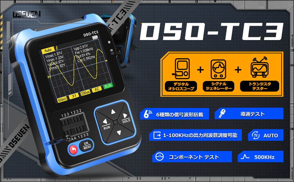
Figure 2.1: Visual representation of the DSO-TC3's integrated functions.
2.1. Digital Oscilloscope
- Real-time sampling rate: 10MS/s
- Bandwidth: 500KHz
- Maximum voltage measurement: 400V
- Trigger functions: Auto, Single, Normal
- Equipped with an efficient AUTO key for quick waveform display.

Figure 2.2: The digital oscilloscope interface displaying a waveform, with examples of its use in measuring mains power and detecting switching power supplies.
2.2. Transistor Tester
- Automatically identifies and measures various transistors, including NPN and PNP triodes, N-channel and P-channel MOSFETs, and JFETs.
- Tests diodes, double diodes, thyristors, resistors, inductors, and capacitors.
- Automatic pin definition detection.

Figure 2.3: The transistor tester in action, demonstrating its ability to detect various component types and their characteristics.
2.3. Function Signal Generator
- Generates 6 types of signal waveforms: Sine wave, Square wave, Pulse wave, Triangle wave, Ramp wave, and DC.
- Output frequency adjustable from 1Hz to 100KHz.
- Output voltage adjustable to 3.3V.
- Output duty cycle adjustable from 0% to 100%.

Figure 2.4: Examples of the six different signal waveforms that can be generated by the device.
3. Physical Features and Design
- Durable ABS material shell for anti-drop protection.
- Concave non-slip design for secure handling.
- Comfortable and easy-to-use buttons.
- 2.4-inch high-resolution display.
- Built-in 1500mAh lithium battery providing approximately 240 minutes of continuous use.
- Type-C charging port for convenient charging.
- Integrated 90° hidden stand for hands-free operation.
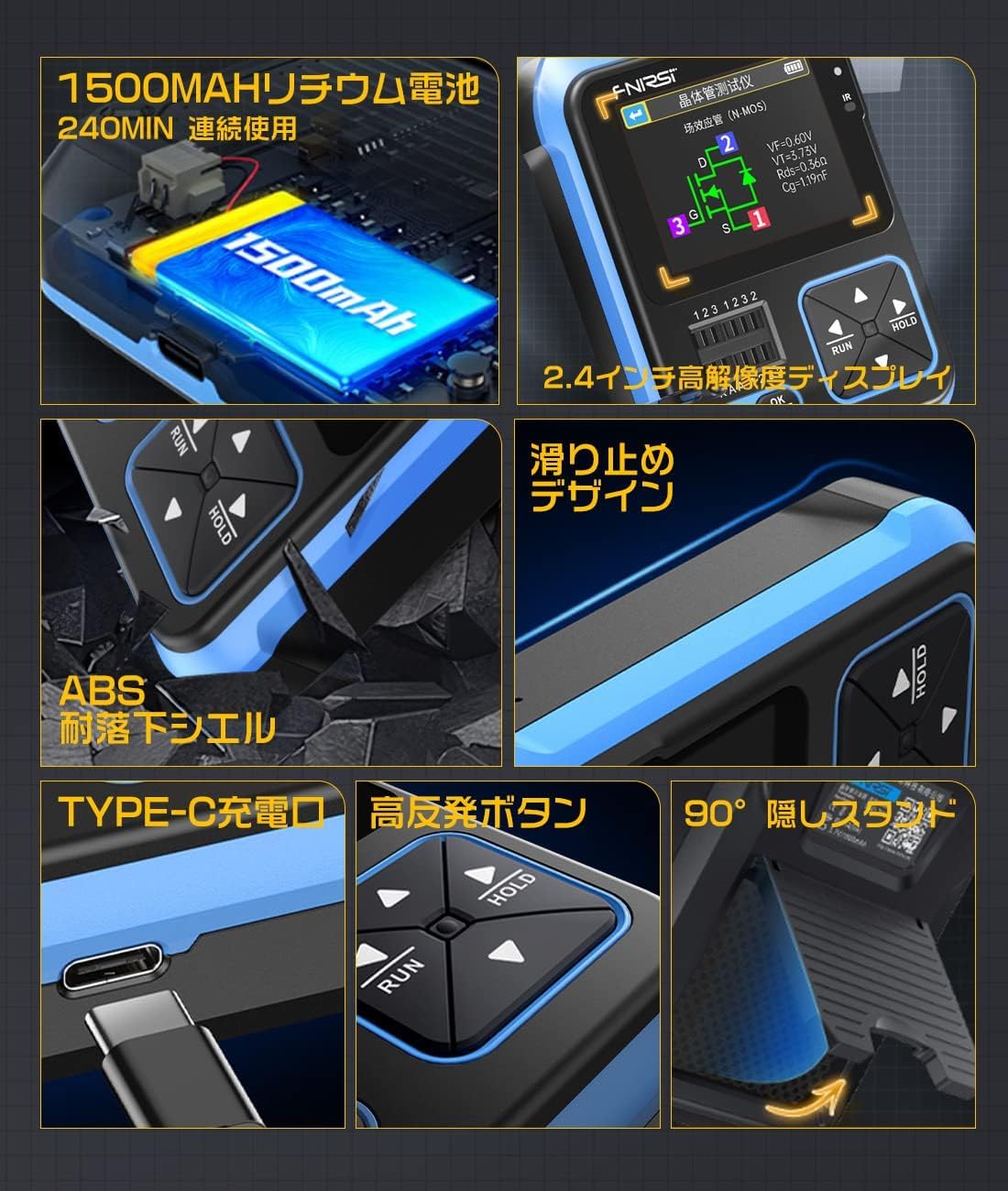
Figure 3.1: Detailed views of the DSO-TC3's physical attributes, highlighting its robust construction and user-friendly design elements.
4. Setup
4.1. Initial Charging
Before first use, fully charge the DSO-TC3 using the provided Type-C USB cable and a compatible USB power adapter (not included). The charging indicator will show the charging status.
4.2. Power On/Off
Press and hold the power button (usually marked with a circle and a line) to turn the device on or off.
4.3. Probe Connection
Connect the appropriate test probes or clips to the input jacks on the device based on the function you intend to use (oscilloscope, transistor tester, or signal generator output).
5. Operating Instructions
5.1. Mode Selection
The DSO-TC3 typically has a main menu or dedicated buttons to switch between its three primary modes: Oscilloscope, Transistor Tester, and Signal Generator. Refer to the on-screen prompts and button labels for navigation.
5.2. Digital Oscilloscope Operation
- Connecting Probes: Attach the oscilloscope probe to the BNC connector.
- Measurement: Connect the probe to the circuit point you wish to measure.
- AUTO Button: Press the AUTO button for automatic waveform scaling and positioning.
- Adjustments: Use the navigation buttons (up/down/left/right) to manually adjust voltage scale (V/div), time base (s/div), and trigger level if needed.
- HOLD Button: Press HOLD to freeze the current waveform display.
5.3. Transistor Tester Operation
- Component Placement: Insert the component leads into the designated test sockets (usually labeled 1, 2, 3, KAA). Ensure proper contact.
- Initiate Test: Press the OK/MENU button or a dedicated test button to start the measurement.
- Results: The device will automatically identify the component type (e.g., NPN, PNP, MOSFET, Diode) and display its parameters (e.g., hFE, V_f, capacitance, resistance, inductance) and pinout.
5.4. Function Signal Generator Operation
- Select Waveform: Navigate through the menu to choose one of the 6 available waveform types (Sine, Square, Pulse, Triangle, Ramp, DC).
- Adjust Parameters: Use the navigation buttons to set the desired frequency (1Hz-100KHz), voltage (up to 3.3V), and duty cycle (0-100% for applicable waveforms).
- Output: The generated signal will be available at the designated output port.
5.5. Tool Box Functions
The DSO-TC3 includes additional utility functions under its 'Tool Box' mode:
- Circuit Continuity Test: Check for open or short circuits.
- 0-40V Input Voltage Measurement: Measure DC voltage within this range.
- PWM Output: Generate Pulse Width Modulation signals.
- 0-32V Zener Diode Measurement: Test Zener diodes.
- DS18B20 Temperature Sensor Measurement: Read data from DS18B20 sensors.
- DHT11 Temperature and Humidity Sensor Measurement: Read data from DHT11 sensors.
- IR Decode: Automatically analyzes NEC protocol infrared codes.
- Calibrate: For device calibration.

Figure 5.1: The Tool Box menu, providing access to advanced diagnostic and measurement utilities.

Figure 5.2: Practical applications of the DSO-TC3 in various fields, from DIY to professional repair and testing.
6. Maintenance
- Cleaning: Use a soft, dry cloth to clean the device. Do not use abrasive cleaners or solvents.
- Storage: Store the device in a cool, dry place away from direct sunlight and extreme temperatures.
- Battery Care: For prolonged storage, charge the battery to about 50% every few months to maintain battery health.
- Probe Care: Inspect test probes and leads regularly for damage. Replace if insulation is cracked or wires are exposed.
7. Troubleshooting
| Problem | Possible Cause | Solution |
|---|---|---|
| Device does not power on | Low battery; Power button not pressed long enough | Charge the device; Press and hold the power button for 3-5 seconds |
| Inaccurate measurements | Incorrect probe connection; Device needs calibration; Component damaged | Ensure probes are correctly connected; Use the 'Calibrate' function in Tool Box; Test with known good components |
| Screen display issues (lines, partial display) | Hardware defect | Contact customer support for assistance or replacement. |
| Signal generator output is weak or absent | Incorrect settings; Loose connection | Verify frequency, voltage, and duty cycle settings; Check cable connections |
8. Specifications
- Model: DSO-TC3
- Brand: OSEVEN
- Dimensions: Approximately 13.8 x 12.2 x 6.4 cm
- Weight: Approximately 290 g
- Display: 2.4-inch High-Resolution Color Display
- Battery: 1500mAh Lithium Battery
- Charging Port: USB Type-C
8.1. Digital Oscilloscope Specifications
- Real-time Sampling Rate: 10MS/s
- Bandwidth: 500KHz
- Maximum Input Voltage: 400V (DC/AC Peak)
- Trigger Modes: Auto, Single, Normal
8.2. Transistor Tester Specifications
- Component Types: NPN/PNP Transistors, MOSFETs (N/P Channel), JFETs, Diodes, Double Diodes, Thyristors, Resistors, Inductors, Capacitors
- Automatic Identification: Yes
8.3. Function Signal Generator Specifications
- Waveform Types: Sine, Square, Pulse, Triangle, Ramp, DC
- Output Frequency Range: 1Hz - 100KHz
- Output Voltage: 3.3V (Adjustable)
- Duty Cycle: 0% - 100% (Adjustable)
9. Warranty and Support
This product comes with a standard manufacturer's warranty. For specific warranty terms, technical support, or service inquiries, please refer to the contact information provided with your purchase or visit the official OSEVEN website. Please retain your proof of purchase for warranty claims.


