
1. Introduction
The SMARTGEN HGM6110CAN-4G series automatic controller is an advanced unit designed for the automatic control and monitoring of genset systems. It integrates digital, intelligent, and network communication technologies to provide comprehensive functionality.
This controller supports automatic start/stop operations, precise data measurement, and robust alarm protection. It also facilitates three remote functions: remote control, remote measurement, and remote communication, enabling comprehensive management from a distance.
Equipped with a clear LCD display and a user-friendly push-button interface, the HGM6110CAN-4G offers reliable operation. Its internal network communication module allows for internet connectivity, enabling real-time data upload to a cloud server. Users can monitor genset status, review event logs, and configure parameters via a dedicated mobile application (iOS or Android) or a computer terminal. The unit also includes SMS functionality for alerts and communication.
2. Key Features
- Display: 132x64 LCD display with backlight, offering eight optional language interfaces including Chinese, English, Spanish, Russian, Portuguese, Turkish, Polish, and French. Features push-button operation.
- Durability: Acrylic screen for improved wear and scratch resistance. Silica-gel panel and keys designed for adaptability to varying temperatures.
- Compatibility: Adaptable to 3P4W, 3P3W, 1P2W, and 2P3W (120V/240V) AC power systems, supporting both 50Hz and 60Hz frequencies.
- Measurement Capabilities: Capable of collecting and displaying 3-phase voltage, 3-phase current, frequency, power parameters for both mains and genset.
- Microprocessor: Utilizes a 32-bit microprocessor for precision measurement, value adjustment, timing, and threshold setting.
- Parameter Configuration: All parameters can be configured directly from the front panel or via a PC using a USB or RS485 interface.
- Remote Connectivity: Integrated network communication module for internet access, cloud server data upload (including GPS positioning and altitude), and remote monitoring via phone APP or computer.
- SMS Functionality: The network communication module also supports SMS functions.
3. Product Overview
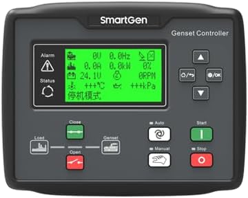
Figure 3.1: Front view of the HGM6110CAN-4G Automatic Controller. This image shows the main display screen, navigation buttons, and control buttons for load, genset, auto, manual, start, and stop functions.

Figure 3.2: Angled view of the HGM6110CAN-4G Controller. This perspective highlights the depth of the unit and the design of its front panel and side casing.
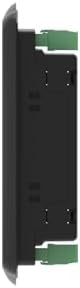
Figure 3.3: Side view of the HGM6110CAN-4G Controller. This image illustrates the slim profile of the unit and the green mounting clips on its sides, indicating how it can be secured into a panel.

Figure 3.4: Rear view of the HGM6110CAN-4G Controller. This view displays the extensive array of connection terminals, including those for genset voltage, mains voltage, auxiliary outputs, and inputs. Also visible are the USB port, SIM card slot, and an inner diagram for wiring reference.
4. Setup and Installation
Proper installation is crucial for the optimal performance and longevity of your HGM6110CAN-4G controller. Refer to the detailed wiring diagram and terminal descriptions for accurate connections.
4.1 Wiring Connections
The controller requires connections for power supply, genset voltage, mains voltage, current transformers, auxiliary inputs, and outputs. Ensure all connections are secure and follow local electrical codes.

Figure 4.1: HGM6110CAN-4G Typical Application Diagram. This comprehensive diagram illustrates the standard wiring connections for the controller, including power inputs (B+, B-), emergency stop, crank, fuel, charger, engine sensors (D+, engine temp, oil pressure, level), magnetic pickup, auxiliary inputs, auxiliary outputs, and connections for RS485-USB module and SG72 module.
4.2 Initial Configuration
After physical installation, the controller's parameters must be configured. This can be done in several ways:
- Front Panel: Basic parameters can be set directly using the push-buttons and LCD display on the controller's front panel.
- USB Interface: Connect the controller to a PC via the USB interface. Use the dedicated SmartGen PC software for comprehensive parameter adjustment.
- RS485 Interface: For remote or integrated system configurations, the RS485 interface allows for PC-based parameter adjustments.
Ensure all system-specific parameters, such as voltage, current transformer ratios, engine type, and alarm thresholds, are correctly set according to your genset and application requirements.
5. Operating Instructions
The HGM6110CAN-4G controller is designed for user-friendly operation, supporting both manual and automatic control modes.
5.1 Control Modes
- Automatic Mode: In this mode, the controller automatically manages the genset's start and stop operations based on predefined conditions, such as mains power status or scheduled events.
- Manual Mode: Allows for direct manual control of the genset's start and stop functions via the front panel buttons.
- Test Mode: For testing the genset without affecting the load.
5.2 Monitoring and Alarms
The LCD display provides real-time data on genset parameters, including voltage, current, frequency, power, engine temperature, oil pressure, and fuel level. The controller continuously monitors these parameters and activates alarms in case of abnormal conditions, protecting the genset from potential damage.
5.3 Remote Operation
Leverage the built-in network communication module for remote monitoring and control:
- Cloud Server: Once connected to the internet, the controller uploads real-time data to the SmartGen cloud server.
- Mobile App/PC Terminal: Access the cloud server via the dedicated mobile application (iOS/Android) or a computer terminal to view genset status, event logs, and perform remote control actions.
- SMS: Receive critical alerts and status updates via SMS messages.
6. Maintenance
Regular maintenance ensures the reliable operation and extends the lifespan of your HGM6110CAN-4G controller. While the unit itself requires minimal maintenance, consider the following:
- Cleaning: Keep the display and panel clean using a soft, dry cloth. Avoid abrasive cleaners or solvents.
- Connections: Periodically check all wiring connections for tightness and signs of corrosion. Loose connections can lead to erratic behavior or damage.
- Firmware Updates: Check the SmartGen-America website for any available firmware updates that may improve performance or add new features.
- Environmental Conditions: Ensure the controller operates within its specified environmental limits (temperature, humidity) to prevent premature failure.
7. Troubleshooting
This section provides general guidance for common issues. For complex problems, consult the detailed troubleshooting guide available on the SmartGen-America website or contact technical support.
| Problem | Possible Cause | Solution |
|---|---|---|
| Controller does not power on. | No power supply; loose wiring; blown fuse. | Check power input (B+ and B- terminals). Verify wiring. Check inline fuses. |
| Genset fails to start in Auto mode. | Auto mode not selected; start conditions not met; engine fault. | Ensure controller is in Auto mode. Verify mains status or start signal. Check engine for fuel, battery, and other faults. |
| Incorrect readings on display. | Incorrect CT ratios; sensor malfunction; wiring error. | Verify CT ratio settings in parameters. Check sensor connections and functionality. Review wiring diagram for correct connections. |
| Cannot connect to cloud server. | No internet connection; incorrect network settings; SIM card issue. | Check network cable/SIM card. Verify APN settings and server address. Ensure SIM card has active data plan. |
8. Specifications
| Parameter | Value |
|---|---|
| Model | HGM6110CAN-4G |
| Brand | SMARTGEN |
| Display Type | 132*64 LCD with backlight |
| Power System Compatibility | 3P4W, 3P3W, 1P2W, 2P3W (120V/240V), 50Hz/60Hz |
| Microprocessor | 32-bit |
| Communication Interfaces | USB, RS485, Network (4G module) |
| Material | Acrylic (screen) |
| Item Weight | 2 pounds (0.91 Kilograms) |
| Manufacturer | SMARTGEN |
9. Warranty and Support
For warranty information, technical support, and detailed product documentation, please visit the official SmartGen-America website or contact their customer service. Keep your purchase receipt for warranty claims.
Manufacturer: SMARTGEN
Seller: SmartGen-America
Return Policy: 30-day refund/replacement policy from the seller.
Protection Plans: Optional 3-Year and 4-Year protection plans may be available for purchase separately.
For the most up-to-date information, refer to the product listing on Amazon or the SmartGen-America official website.
