1. Introduction
The SMARTGEN HGM6110N-4G Automatic Controller is an advanced device designed for the automatic control and monitoring of gensets. It integrates digital, intelligent, and network communication technologies to provide comprehensive management capabilities. This controller supports automatic start/stop operations, precise data measurement, robust alarm protection, and 'three remote' functions: remote control, remote measurement, and remote communication.
Equipped with a 132x64 LCD display, the HGM6110N-4G offers an intuitive user interface with support for eight optional languages, including Chinese, English, Spanish, Russian, Portuguese, Turkish, Polish, and French. Its operation is simplified through push-buttons. The controller's durable design features an acrylic screen for improved wear and scratch resistance, and a silica-gel panel and keys that adapt well to varying temperatures.
A key feature is its integrated network communication module, enabling the genset to connect to the internet. Once logged into a cloud server, unit data, including GPS positioning and altitude, is uploaded in real-time. Users can monitor the genset, inquire about its running status, review event logs, and configure parameters remotely via a dedicated phone application (iOS or Android) or a computer terminal. The network module also provides SMS functionality for alerts and control.
The HGM6110N-4G series utilizes a 32-bit microprocessor for precision measurement, value adjustment, timing, and threshold settings. All parameters can be configured directly from the front panel or adjusted via a PC using a USB or RS485 interface. Its compact structure, simple connections, and high reliability make it suitable for a wide range of automatic control systems.
2. Setup and Installation
Proper installation is crucial for the optimal performance and longevity of your HGM6110N-4G controller. Follow these guidelines carefully.
2.1 Physical Installation
The controller is designed for panel mounting. Ensure the mounting location is secure, free from excessive vibration, and within the specified operating temperature range. Allow adequate space for wiring and ventilation around the unit.
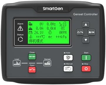
Figure 2.1: Front view of the HGM6110N-4G Automatic Controller, showing the LCD display and control buttons. This is the primary interface for user interaction and monitoring.

Figure 2.2: Angled view of the HGM6110N-4G Automatic Controller, providing a perspective of its compact form factor and panel-mount design.
2.2 Electrical Connections
All electrical connections should be performed by qualified personnel, adhering to local and national electrical codes. Ensure power is disconnected before making any connections.

Figure 2.3: Rear view of the HGM6110N-4G Automatic Controller, highlighting the various green terminal blocks for electrical connections. These include inputs for sensors, power, and outputs for control.

Figure 2.4: Comprehensive rear view of the HGM6110N-4G Automatic Controller, displaying all connection terminals and an internal diagram. This view is essential for understanding the wiring layout and connecting external components.
2.3 Wiring Diagram
Refer to the typical application diagram for detailed wiring instructions. This diagram illustrates the connections for power, sensors, outputs, and communication interfaces.

Figure 2.5: HGM6110N-4G Typical Application Diagram, illustrating the standard electrical connections for the controller within a genset system. This includes connections for generator output, load, battery, fuel, engine temperature, oil pressure, and auxiliary inputs/outputs.
The controller is compatible with 3P4W, 3P3W, 1P2W, and 2P3W (120V/240V) AC power systems, operating at 50Hz/60Hz. Ensure your genset's power system matches these specifications.
2.4 Initial Power-up and Configuration
After all connections are secure, apply power to the controller. The LCD display will illuminate. Initial configuration can be performed via the front panel buttons or by connecting to a PC using the USB or RS485 interface and the appropriate software. Refer to the detailed programming manual for parameter settings.
3. Operating Instructions
The HGM6110N-4G controller offers various operating modes and functions for efficient genset management.
3.1 Display and Navigation
The 132x64 LCD display provides real-time operational data, alarms, and status information. Use the push-buttons on the front panel to navigate through menus, view parameters, and acknowledge alarms. The display offers multiple language options for user convenience.
3.2 Automatic Start/Stop
The controller can be configured for automatic start and stop sequences based on predefined conditions, such as mains failure, low battery voltage, or scheduled operation. Ensure all necessary sensors and actuators are correctly connected and calibrated for reliable automatic operation.
3.3 Remote Functions ('Three Remote')
The HGM6110N-4G supports three remote functions:
- Remote Control: Start, stop, or change operating modes of the genset from a remote location.
- Remote Measurement: Access real-time operational data (e.g., voltage, current, frequency, engine parameters) remotely.
- Remote Communication: Utilize the RS485 communication port with MODBUS protocol or the internal network communication module for data exchange with a PC or cloud server.
For cloud-based remote monitoring, ensure the controller is connected to a stable internet connection and registered with the SMARTGEN cloud server. Download the official mobile application (iOS or Android) or access the web portal for remote access.
4. Maintenance
Regular maintenance ensures the longevity and reliable operation of your HGM6110N-4G controller.
4.1 Cleaning
Periodically clean the controller's front panel with a soft, dry cloth. Avoid using abrasive cleaners or solvents that could damage the acrylic screen or silica-gel panel. Ensure no dust or debris accumulates around the buttons or display.
4.2 Connection Checks
Inspect all wiring connections periodically to ensure they are secure and free from corrosion. Loose connections can lead to intermittent operation or false readings.
4.3 Firmware Updates
Check the SMARTGEN website or contact support for information on available firmware updates. Keeping the controller's firmware up-to-date can provide new features, performance improvements, and bug fixes. Follow the provided instructions carefully when performing updates.
5. Troubleshooting
This section provides guidance for common issues you might encounter with the HGM6110N-4G controller.
5.1 Common Issues and Solutions
- Controller does not power on: Check the main power supply to the controller. Verify all power connections are secure and correctly wired according to the diagram.
- Genset fails to start automatically: Ensure the automatic start conditions are met (e.g., mains failure detected, remote start signal active). Check all relevant sensor inputs and output connections to the genset starter. Review alarm logs on the controller for specific fault indications.
- Incorrect readings on display: Verify sensor connections and calibration settings. Ensure the correct type of sensor is used for each input (e.g., engine temperature, oil pressure).
- Remote communication issues: Check network cable connections or cellular signal strength for the internal communication module. Verify cloud server registration and account status. For RS485, ensure correct wiring, baud rate, and MODBUS address settings.
- Alarms persist: Identify the specific alarm code displayed on the LCD. Refer to the detailed product manual for a comprehensive list of alarm codes and their corresponding troubleshooting steps. Address the root cause of the alarm before resetting.
If an issue persists after attempting these troubleshooting steps, contact SMARTGEN technical support for further assistance.
6. Specifications
Below are the key technical specifications for the HGM6110N-4G Automatic Controller:
| Feature | Specification |
|---|---|
| Model | HGM6110N-4G |
| Display | 132*64 LCD with backlight |
| Interface Languages | Chinese, English, Spanish, Russian, Portuguese, Turkish, Polish, French |
| Operation | Push-button operation |
| Screen Material | Acrylic (improved wearable and scratch resistance) |
| Panel Material | Silica-gel (adapts to higher and lower temperature) |
| Communication Port | RS485 (MODBUS protocol for 'three remote' functions) |
| Network Communication | Internal module for internet access, cloud server data upload, SMS function |
| Power System Compatibility | 3P4W, 3P3W, 1P2W, 2P3W (120V/240V), 50Hz/60Hz AC |
| Microprocessor | 32-bit |
| Item Weight | 2 pounds (0.91 Kilograms) |
| Manufacturer | SMARTGEN |
7. Warranty and Support
7.1 Product Warranty
For specific warranty terms and conditions, please refer to the documentation provided with your purchase or contact SMARTGEN directly. Standard manufacturer warranties typically cover defects in materials and workmanship for a specified period from the date of purchase.
7.2 Technical Support
If you require technical assistance, have questions about installation, operation, or troubleshooting that are not covered in this manual, please contact the seller, SmartGen-America, or visit the official SMARTGEN website for support resources and contact information.


