
1. Introduction
The Tekpower TP107+ is a digital True-RMS automotive multimeter designed for precise electrical and automotive measurements. It features a 6,000-count LCD display with backlight and offers a wide range of functions including DC/AC voltage, current, resistance, temperature, capacitance, 12V battery testing, RPM, pulse width, and dwell angle measurements. This manual provides essential information for the safe and effective operation of your device.
2. Safety Information
Always adhere to basic safety precautions when using this multimeter to prevent personal injury or damage to the device or equipment under test. Improper use can result in electric shock or fire.
- Read the Manual: Familiarize yourself with the operation and safety instructions before use.
- Inspect Before Use: Check the multimeter and test leads for any damage before each use. Do not use if damaged.
- Voltage Limits: Do not exceed the maximum input values specified for each function.
- Proper Function Selection: Ensure the rotary switch is set to the correct function and range before making measurements.
- Live Circuits: Exercise extreme caution when working with live circuits. Avoid contact with bare wires or terminals.
- Fuse Protection: The device features dual fused protection. Replace fuses only with specified types and ratings.
- Battery Replacement: Replace batteries promptly when the low battery indicator appears to ensure accurate readings.
- Environmental Conditions: Use the multimeter in dry conditions. Avoid use in high humidity or explosive environments.
3. Product Overview
The Tekpower TP107+ multimeter features a robust design with a clear LCD display and intuitive controls.
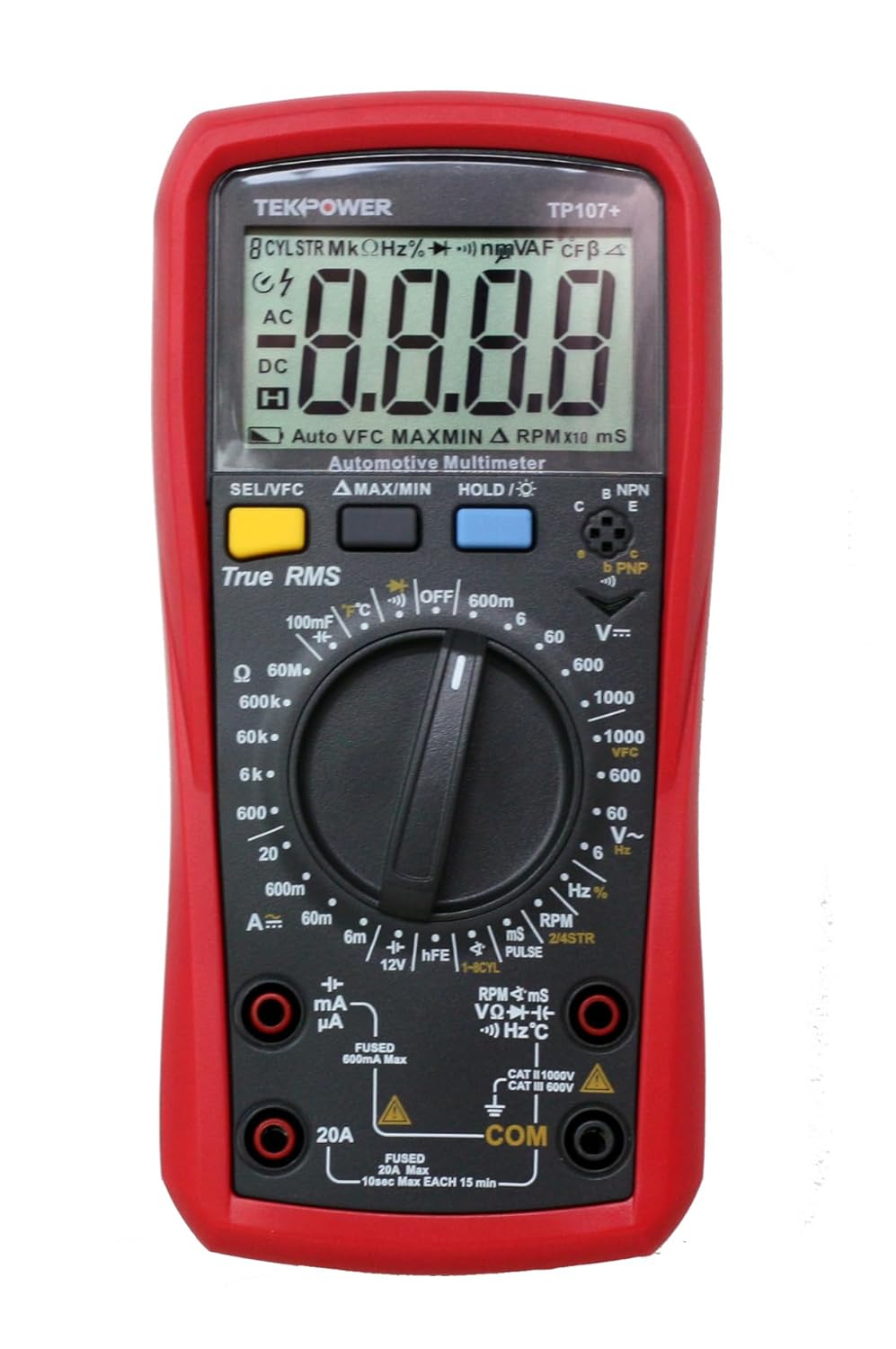
Figure 3.1: Front view of the Tekpower TP107+ Digital True-RMS Automotive Multimeter, showing the display, rotary switch, and input jacks.
3.1. Components
- LCD Display: 6,000-count, backlit display for clear readings.
- Rotary Switch: Used to select measurement functions and ranges.
- Function Buttons: Include SEL/VFC, ΔMAX/MIN, HOLD/⌂ for additional features.
- Input Jacks: Dedicated jacks for various measurements (VΩHz, mAμA, 20A, COM).
- Kickstand: Integrated kickstand for convenient hands-free operation.

Figure 3.2: Rear view of the multimeter with the kickstand extended, providing an angled display for easier viewing.
4. Setup
4.1. Battery Installation
The TP107+ requires two AAA batteries (included). To install or replace batteries:
- Ensure the multimeter is turned off.
- Locate the battery compartment on the back of the unit.
- Use a screwdriver to open the battery compartment cover.
- Insert two AAA batteries, observing the correct polarity (+/-) as indicated inside the compartment.
- Replace the battery compartment cover and secure it with the screw.
4.2. Connecting Test Leads
Proper connection of test leads is crucial for accurate and safe measurements. The multimeter includes test leads and a thermo probe.

Figure 4.1: The TP107+ multimeter shown with its included test leads and thermo probe, ready for connection.
- Connect the black test lead to the COM (Common) input jack.
- For most voltage, resistance, frequency, capacitance, and temperature measurements, connect the red test lead to the VΩHz input jack.
- For current measurements up to 600mA, connect the red test lead to the mAμA input jack.
- For high current measurements up to 20A, connect the red test lead to the 20A input jack.
- For temperature measurements, connect the thermo probe to the appropriate input jacks as indicated in the manual.
5. Operating Instructions
Turn the rotary switch to the desired function. The display will show the measurement. Use the 'SEL/VFC' button to switch between sub-functions if available (e.g., AC/DC, VFC).
5.1. DC Voltage Measurement (V⌂)
Connect the red lead to VΩHz and the black lead to COM. Set the rotary switch to the V⌂ range. The multimeter measures DC voltage from 600mV to 1000V.
5.2. AC Voltage Measurement (V∼)
Connect the red lead to VΩHz and the black lead to COM. Set the rotary switch to the V∼ range. The multimeter measures AC voltage from 6V to 1000V at 40-400Hz. This is a True-RMS measurement.
5.3. VFC Function (Voltage Frequency Converter)
In AC Voltage mode, press the 'SEL/VFC' button to activate the VFC function. This function is useful for measuring AC voltage in variable frequency drive (VFD) circuits, filtering out PWM frequency to accurately measure RMS voltage into a motor.
5.4. DC Current Measurement (A⌂, mA⌂, μA⌂)
Connect the red lead to mAμA or 20A (depending on expected current) and the black lead to COM. Set the rotary switch to the appropriate A⌂ range. Measures DC current from 6mA to 20A.
5.5. AC Current Measurement (A∼, mA∼, μA∼)
Connect the red lead to mAμA or 20A and the black lead to COM. Set the rotary switch to the appropriate A∼ range. Measures AC current from 6mA to 20A.
5.6. Resistance Measurement (Ω)
Connect the red lead to VΩHz and the black lead to COM. Set the rotary switch to the Ω range. Measures resistance from 600Ω to 60MΩ.
5.7. Temperature Measurement (°C/°F)
Connect the thermo probe to the designated input jacks. Set the rotary switch to the temperature function. Measures temperature from -40 to 1000°C or -40 to 1832°F.
5.8. Capacitance Measurement (F)
Connect the red lead to VΩHz and the black lead to COM. Set the rotary switch to the capacitance function. Measures capacitance from 6nF to 100mF.
5.9. 12V Battery Test
Set the rotary switch to the 12V battery test function. Connect the leads to the 12V battery terminals. The multimeter applies a built-in 240 ohm load to test the battery under load conditions.
5.10. Tachometer (RPM)
Set the rotary switch to the RPM function. Select 2-stroke or 4-stroke engine type. Connect the appropriate lead for RPM measurement. Measures RPM from 300-19,999 (2-stroke) or 600-19,999 (4-stroke).
5.11. Dwell Angle Measurement
Set the rotary switch to the Dwell function. Select the number of cylinders (1, 2, 3, 4, 5, 6, or 8). Connect the appropriate lead for dwell angle measurement.
5.12. Pulse Width Measurement
Set the rotary switch to the Pulse Width function. Measures pulse width from 0 to 999.9 ms.
5.13. Duty Cycle Measurement
Set the rotary switch to the Duty Cycle function. Measures duty cycle from 10% to 90%.
5.14. Diode Test
Set the rotary switch to the Diode Test function. Connect the leads across the diode. The display shows the forward voltage drop.
5.15. Continuity Test
Set the rotary switch to the Continuity Test function. Connect the leads across the circuit. An audible tone indicates continuity.
5.16. Special Features
- Manual Range Control: Manually select the measurement range for precision.
- Back-lit LCD Display: Press the backlight button for improved visibility in low-light conditions.
- Max/Min Measurement: Press the ΔMAX/MIN button to record maximum and minimum readings.
- Data Hold: Press the HOLD/⌂ button to freeze the current reading on the display.
- Auto-off: The multimeter automatically powers off after a period of inactivity to conserve battery life.
- Low Battery Indicator: An icon on the display indicates when batteries need replacement.
- Over Range "1" Display: Indicates that the measured value exceeds the selected range.
6. Maintenance
6.1. Cleaning
Wipe the case with a damp cloth and mild detergent. Do not use abrasives or solvents. Ensure the device is dry before use.
6.2. Fuse Replacement
The TP107+ features dual fused protection. If the current measurement function fails, the fuse may need replacement. Refer to the internal diagram for fuse specifications and replacement procedures. Always replace with fuses of the identical type and rating.
7. Troubleshooting
- No Display/Faint Display: Check battery installation and charge level. Replace batteries if necessary.
- Incorrect Readings: Ensure test leads are correctly connected to the appropriate input jacks. Verify the rotary switch is set to the correct function and range for the measurement. Check for damaged test leads.
- Current Measurement Not Working: Check the fuse. Replace if blown.
- RPM Function Issues: Ensure proper connection to the ignition system and correct cylinder/stroke settings are selected. Verify the signal source is strong and stable.
- "OL" Display: Indicates an over-range condition. Select a higher range or verify the circuit is not open.
8. Specifications
| Measurement | Range/Accuracy |
|---|---|
| DC Voltage | 600mV, 6V ±0.5%; 60V, 600V, 1000V ±0.7% (Impedance: 10 MΩ) |
| AC Voltage | 6V ±1.0%; 60V, 600V ±0.8%; 1000V ±1.0% (40-400Hz, Impedance: 10 MΩ) |
| VFC | 1000V ±2.0% (40-200Hz, Impedance: 10 MΩ) |
| DC Current | 6mA ±0.8%; 60mA, 600mA ±1.2%; 20A ±2.0% |
| AC Current | 6mA ±1.0%; 60mA, 600mA ±2.0%; 20A ±3.0% |
| Resistance | 600Ω, 6KΩ, 60KΩ, 600KΩ ±0.8%; 60MΩ ±2.0% |
| Temperature | -40 to 100°C ±1%, 100-1000°C ±2% | -40 to 212°F ±1.5%, 212-1832°F ±2.5% |
| Capacitance | 6nF, 60nF, 600nF ±4%; 6μF, 60μF, 600μF ±3%; 6mF ±5%; 60mF, 100mF ±10% |
| 12V Battery Test | ±2.5% (with built-in 240Ω load) |
| Tachometer (RPM) | 2/4 stroke selectable, 300-19,999 RPM (2STR), 600-19,999 RPM (4STR) ±3.0% |
| Dwell Angle | 1, 2, 3, 4, 5, 6, 8 cylinders selectable ±3.0% |
| Pulse Width | 0-999.9 ms ±2.6% |
| Duty Cycle | 10%-90% ±1.5% |
| Diode Test | Yes |
| Continuity Test | Yes (with audible indicator) |
| Dimensions | 179 x 88 x 39 mm (7.2 x 3.46 x 2.2 inches) |
| Weight | 380 grams (12.28 ounces) |
| Batteries | 2 AAA batteries (included) |
9. What's in the Box
Upon unpacking your Tekpower TP107+ multimeter, you should find the following items:
- TP107+ Automotive Multimeter
- Test Leads (one red, one black)
- Thermo Probe
- AAA Batteries (2, pre-installed)
- User Manual (this document)
10. Warranty and Support
The Tekpower TP107+ comes with a 1-year USA manufacturer's warranty. For technical support, warranty service, or any inquiries, please contact Tekpower directly. Tekpower maintains a corporate headquarters in the greater Los Angeles area and offers a toll-free hotline for bi-lingual (English/Spanish) technical support and warranty service.
Please refer to the official Tekpower website or the packaging for the most current contact information.